Nissan Versa Sedan. Instruction - part 498


  Index      Nissan     Nissan Versa Sedan (2014 year) - Service and Repair Instruction


Search            copyright infringement  


Content   ..  496  497  498  499   ..


Nissan Versa Sedan. Instruction - part 498


COMPRESSOR DOES NOT OPERATE

HAC-47

< SYMPTOM DIAGNOSIS >

[MANUAL AIR CONDITIONING]

C

D

E

F

G

H

J

K

L

M

A

B

HAC

N

O

P

COMPRESSOR DOES NOT OPERATE

Description

INFOID:0000000009269813

SYMPTOM

Compressor does not operate. 

Diagnosis Procedure

INFOID:0000000009269814

NOTE:

• Perform self-diagnosis with CONSULT before performing symptom diagnosis. If any malfunction result or

DTC is detected, perform the corresponding diagnosis.

• Check that refrigerant system is fully charged. If the refrigerant charge is low, perform the inspection for

refrigerant leakage

1.

CHECK MAGNET CLUTCH OPERATION

Check magnet clutch. Refer to 

HAC-42, "Component Function Check"

Does it operate normally?

YES

>> GO TO 2.

NO

>> Repair or replace malfunctioning parts.

2.

CHECK REFRIGERANT PRESSURE SENSOR

Check refrigerant pressure sensor. Refer to 

EC-448, "Component Function Check"

.

Is the inspection result normal?

YES

>> GO TO 3.

NO

>> Repair or replace malfunctioning parts.

3.

CHECK A/C ON SIGNAL

Check A/C ON signal. Refer to 

HAC-32, "Component Function Check"

.

Is the inspection result normal?

YES

>> GO TO 4.

NO

>> Repair or replace malfunctioning parts. 

4.

CHECK BLOWER FAN ON SIGNAL

Check blower fan ON signal. Refer to 

HAC-35, "Component Function Check"

.

Is the inspection result normal?

YES

>> GO TO 5.

NO

>> Repair or replace malfunctioning parts

5.

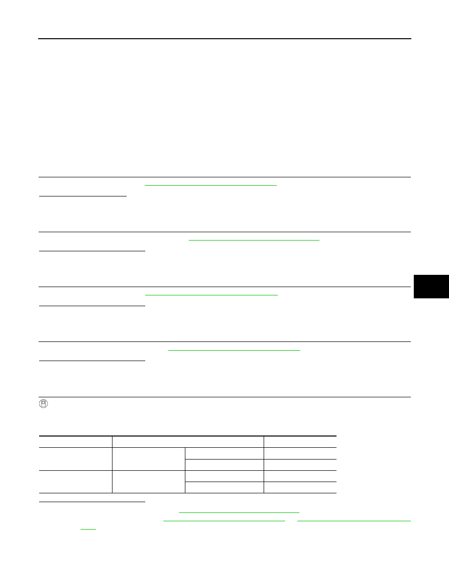
CHECK BCM OUTPUT SIGNAL

With CONSULT

1. Select “DATA MONITOR” mode of “ECM” using CONSULT.

2. Select “AIR COND SIG” and “HEATER FAN SW”, and check status under the following conditions.

Is the inspection result normal?

YES

>> Replace IPDM E/R. Refer to 

PCS-56, "Removal and Installation"

.

NO

>> Replace BCM. Refer to 

BCS-69, "Removal and Installation"

 or 

BCS-122, "Removal and Installa-

tion"

.

Monitor item

Condition

Status

AIR COND SIG

A/C switch

OFF (A/C indicator: OFF)

Off

ON (A/C indicator: ON)

On

HEATER FAN SW

Blower motor

OFF

Off

ON

On

HAC-48

< UNIT REMOVAL AND INSTALLATION >

[MANUAL AIR CONDITIONING]

FRONT AIR CONTROL

UNIT REMOVAL AND INSTALLATION

FRONT AIR CONTROL

Exploded View

INFOID:0000000009269815

Removal and Installation

INFOID:0000000009269816

REMOVAL

1. Remove A/C finisher. Refer to 

IP-21, "Removal and Installation"

.

2. Remove the air mix door cable from the A/C unit assembly. Refer to 

HAC-52, "AIR MIX DOOR CABLE :

Removal and Installation"

.

3. Remove the mode door cable from the A/C unit assembly. Refer to 

HAC-52, "MODE DOOR CABLE :

Removal and Installation"

.

4. Remove the intake door cable from the A/C unit assembly. Refer to 

HAC-51, "INTAKE DOOR CABLE :

Removal and Installation"

.

5. Remove the front air control screws.
6. Remove the front air control.

INSTALLATION

Installation is in the reverse order of removal.

1.

Mode door cable

2.

Illumination bulb

3.

Air mix door cable

4.

Front air control

5.

Intake door cable

6.

Intake door lever knob

7.

Control panel bezel

8.

Mode dial

9.

Temperature dial

10. Fan control dial

A.

To mode door link

B.

To air mix door link

C.

To intake door link

JMIIA0753ZZ

REFRIGERANT PRESSURE SENSOR

HAC-49

< UNIT REMOVAL AND INSTALLATION >

[MANUAL AIR CONDITIONING]

C

D

E

F

G

H

J

K

L

M

A

B

HAC

N

O

P

REFRIGERANT PRESSURE SENSOR

Removal and Installation for Refrigerant Pressure Sensor

INFOID:0000000009269817

REMOVAL

CAUTION:

• Do not damage the condenser fins.

• Perform lubricant return operation before each refrigeration

system disassembly. However, if a large amount of refrigerant

or lubricant is detected, do not perform lubricant return oper-

ation. Refer to 

HA-21, "Perform Oil Return Operation"

.

1. Move air guide aside.
2. Disconnect the harness connector from the refrigerant pressure

sensor.

3. Remove the refrigerant pressure sensor (1) from the liquid tank

on the condenser.

INSTALLATION

Installation is in the reverse order of removal.

CAUTION:

• Replace O-ring with new one. Then apply compressor oil to them when installing.

• Check for leakages when recharging refrigerant. Refer to 

HA-17, "Leak Test"

.

ALIIA0004ZZ

HAC-50

< UNIT REMOVAL AND INSTALLATION >

[MANUAL AIR CONDITIONING]

BLOWER FAN RESISTOR

BLOWER FAN RESISTOR

Exploded View

INFOID:0000000009269818

Removal and Installation

INFOID:0000000009269819

REMOVAL

1. Remove instrument panel assembly. Refer to 

IP-15, "Removal and Installation"

.

2. Disconnect harness connector from the blower fan resistor.
3. Remove screws and blower fan resistor.

INSTALLATION

Installation is in the reverse order of removal.

1.

A/C unit assembly

2.

Blower motor

3.

Blower fan resistor

AWIIA1465ZZ


Content   ..  496  497  498  499   ..