Nissan Versa Sedan. Instruction - part 452
FSU-16
< REMOVAL AND INSTALLATION >
FRONT SUSPENSION MEMBER
FRONT SUSPENSION MEMBER
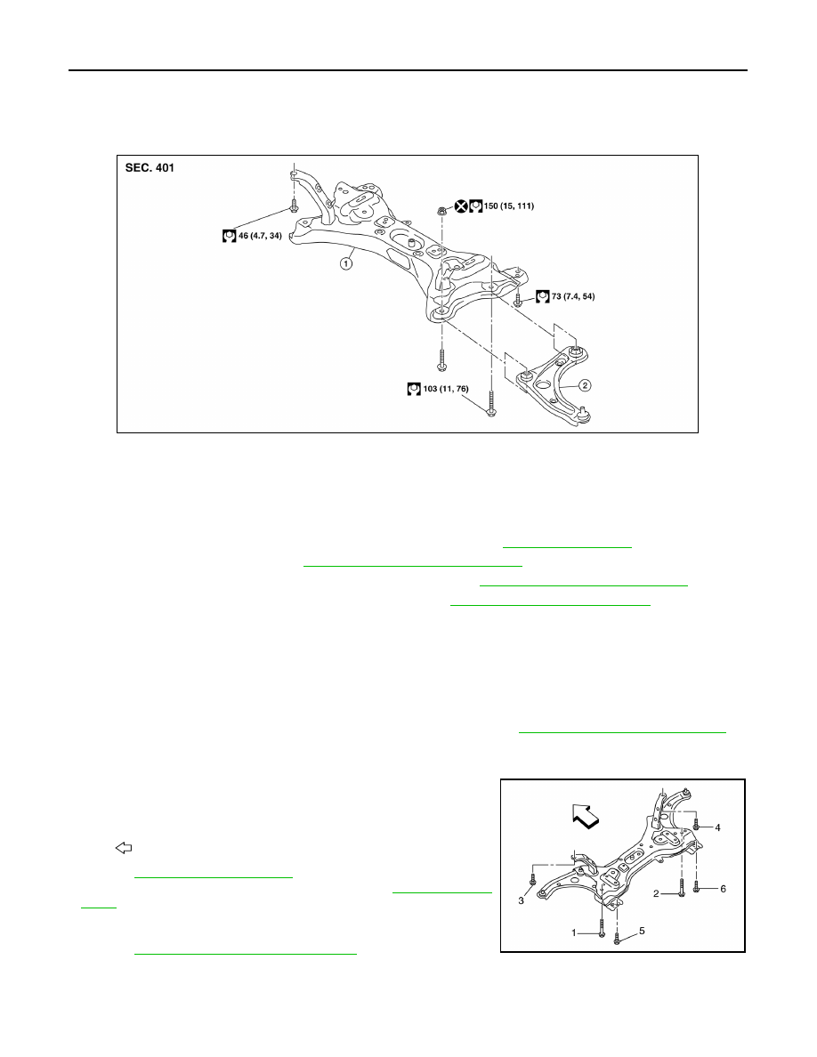
Exploded View
INFOID:0000000009267408
Removal and Installation
INFOID:0000000009267409
REMOVAL
1. Remove the wheel and tire assemblies using power tool. Refer to
2. Remove transverse link. Refer to
FSU-12, "Removal and Installation"
3. Remove steering outer socket from steering knuckle. Refer to
ST-14, "Removal and Installation"
4. Separate intermediate shaft from the lower joint. Refer to
ST-9, "Removal and Installation"
.
5. Remove the engine rear torque rod.
6. Set suitable jack under front suspension member.
CAUTION:
Do not damage the front suspension member with jack.
7. Remove suspension member bolts.
8. Gradually lower the jack to remove front suspension member from vehicle body.
9. Remove steering gear assembly from suspension member. Refer to
ST-14, "Removal and Installation"
.
INSTALLATION
Installation is in the reverse order of removal.
• For installation of the suspension member, temporarily tighten the
bolts in the sequence shown and tighten them to the specified
torque.
• Refer to
for tightening torque.
• Tighten the wheel nuts to specification. Refer to
.
• After installation, perform final tightening of each part under
unladen conditions with tires on ground. Check wheel alignment.
FSU-6, "Inspection and Adjustment"
.
1.
Front suspension member
2.
Transverse link
AWEIA0210GB
: Front
AWEIA0211ZZ