Nissan Versa Sedan. Instruction - part 443


  Index      Nissan     Nissan Versa Sedan (2014 year) - Service and Repair Instruction


Search            copyright infringement  


Content   ..  441  442  443  444   ..


Nissan Versa Sedan. Instruction - part 443


FAX-24

< SERVICE DATA AND SPECIFICATIONS (SDS) 

SERVICE DATA AND SPECIFICATIONS (SDS)

SERVICE DATA AND SPECIFICATIONS (SDS)

SERVICE DATA AND SPECIFICATIONS (SDS)

Wheel Bearing

INFOID:0000000009268304
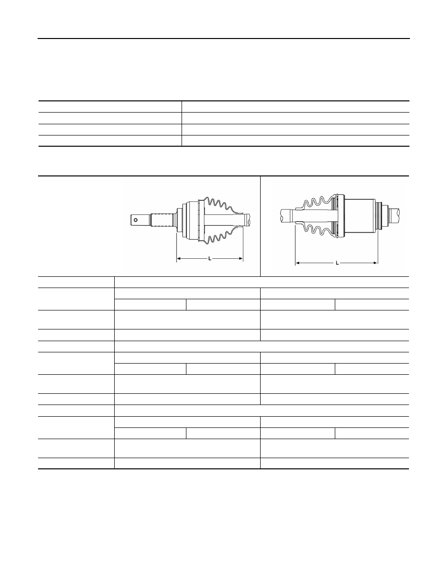
Drive Shaft

INFOID:0000000009268305

Item

Standard

Axial end play

0.055 mm (0.002 in) or less

Rotating torque

1.9 N·m (0.19 kg-m, 17 in-lb) or less

Spring balance measurement

13.7 N (1.40 kg-f, 3.08 lb-f) or less

Application

M/T

Joint type

Wheel side

Transaxle side

LH

RH

LH

RH

Grease quantity

90 - 100 g

(3.17 - 3.53 oz)

141.1- 157.1 g

(4.98 - 5.54 oz)

Boot installed length (L)

135.5 mm (5.33 in)

154 mm (6.06 in)

Application

CVT

Joint type

Wheel side

Transaxle side

LH

RH

LH

RH

Grease quantity

90 - 100 g

(3.17 - 3.53 oz)

132.7 - 148.7 g
(4.68 - 5.25 oz)

Boot installed length (L)

136.8 mm (5.39 in)

145.5 mm (5.73 in)

Application

A/T

Joint type

Wheel side

Transaxle side

LH

RH

LH

RH

Grease quantity

90 - 100 g

(3.17 - 3.53 oz)

132.7 - 148.7 g
(4.68 - 5.25 oz)

Boot installed length (L)

136.8 mm (5.39 in)

145.5 mm (5.73 in)

ALDIA0269ZZ

ALDIA0268ZZ

SERVICE DATA AND SPECIFICATIONS (SDS)

FAX-25

< SERVICE DATA AND SPECIFICATIONS (SDS) 

C

E

F

G

H

I

J

K

L

M

A

B

FAX

N

O

P

Dynamic Damper

INFOID:0000000009268306

Unit: mm (in)

Boot Bands

INFOID:0000000009268307

Unit: mm (in)

Application

M/T

A/T

CVT

LH

RH

LH

RH

LH

RH

Dimension (A)

240 

± 3 (9.45 ± 

0.1)

457 

± 3 (17.99 ± 

0.1)

240 

± 3 (9.45 ± 

0.1)

457 

± 3 (17.99 ± 

0.1)

242.9 

± 3 (9.56 ± 

0.1)

457 

± 3 (17.99 ± 

0.1)

Dimension (B)

70 (2.76)

70 (2.76)

70 (2.76)

ALDIA0270ZZ

Dimension (M) - maximum

7.0 (0.28)

AWDIA0598ZZ

FL-1

ENGINE

C

D

E

F

G

H

I

J

K

L

M

SECTION 

FL

A

FL

N

O

P

CONTENTS

FUEL SYSTEM

PRECAUTION ...............................................

2

PRECAUTIONS ...................................................

2

Precaution for Supplemental Restraint System 
(SRS) "AIR BAG" and "SEAT BELT PRE-TEN-
SIONER" .................................................................
..

2

General Precautions  .................................................

2

PREPARATION ............................................

3

PREPARATION ...................................................

3

Special Service Tool  .................................................

3

Commercial Service Tools  ........................................

3

PERIODIC MAINTENANCE ..........................

4

FUEL SYSTEM ....................................................

4

Inspection ..................................................................

4

Quick Connector  .......................................................

4

REMOVAL AND INSTALLATION ................

5

FUEL LEVEL SENSOR UNIT, FUEL FILTER 
AND FUEL PUMP ASSEMBLY  ..........................

5

Exploded View  ..........................................................

5

Removal and Installation ...........................................

5

FUEL TANK .........................................................

9

Exploded View  ..........................................................

9

Removal and Installation ...........................................

9

Inspection ................................................................

11

EVAP CANISTER ..............................................

12

Exploded View .........................................................

12

Removal and Installation  .........................................

12

Inspection ................................................................

13

EVAP CANISTER FILTER  ................................

14

Exploded View .........................................................

14

Removal and Installation  .........................................

14

EVAP CANISTER VENT CONTROL VALVE  ...

15

Exploded View .........................................................

15

Removal and Installation  .........................................

15

EVAP CONTROL SYSTEM PRESSURE SEN-
SOR ...................................................................

16

Exploded View .........................................................

16

Removal and Installation  .........................................

16

UNIT DISASSEMBLY AND ASSEMBLY  ....

17

FUEL LEVEL SENSOR UNIT  ...........................

17

Disassembly and Assembly .....................................

17

SERVICE DATA AND SPECIFICATIONS 
(SDS) ............................................................

19

SERVICE DATA AND SPECIFICATIONS 
(SDS) .................................................................

19

Fuel Tank .................................................................

19

FL-2

< PRECAUTION >

PRECAUTIONS

PRECAUTION

PRECAUTIONS

Precaution for Supplemental Restraint System (SRS) "AIR BAG" and "SEAT BELT 
PRE-TENSIONER"

INFOID:0000000009267696

The Supplemental Restraint System such as “AIR BAG” and “SEAT BELT PRE-TENSIONER”, used along

with a front seat belt, helps to reduce the risk or severity of injury to the driver and front passenger for certain

types of collision. This system includes seat belt switch inputs and dual stage front air bag modules. The SRS

system uses the seat belt switches to determine the front air bag deployment, and may only deploy one front

air bag, depending on the severity of a collision and whether the front occupants are belted or unbelted.

Information necessary to service the system safely is included in the SR and SB section of this Service Man-

ual.

WARNING:

• To avoid rendering the SRS inoperative, which could increase the risk of personal injury or death in

the event of a collision which would result in air bag inflation, all maintenance must be performed by

an authorized NISSAN/INFINITI dealer.

• Improper maintenance, including incorrect removal and installation of the SRS, can lead to personal

injury caused by unintentional activation of the system. For removal of Spiral Cable and Air Bag

Module, see the SR section.

• Do not use electrical test equipment on any circuit related to the SRS unless instructed to in this

Service Instruction. SRS wiring harnesses can be identified by yellow and/or orange harnesses or har-

ness connectors.

PRECAUTIONS WHEN USING POWER TOOLS (AIR OR ELECTRIC) AND HAMMERS

WARNING:

• When working near the Airbag Diagnosis Sensor Unit or other Airbag System sensors with the Igni-

tion ON or engine running, DO NOT use air or electric power tools or strike near the sensor(s) with a

hammer. Heavy vibration could activate the sensor(s) and deploy the air bag(s), possibly causing

serious injury.

• When using air or electric power tools or hammers, always switch the Ignition OFF, disconnect the

battery, and wait at least 3 minutes before performing any service.

General Precautions

INFOID:0000000009267697

WARNING:

When replacing fuel line parts, be sure to observe the following.

• Put a “CAUTION: FLAMMABLE” sign in the workshop.

• Be sure to work in a well ventilated area and furnish workshop with a CO

2

 fire extinguisher. 

• Do not smoke while servicing fuel system. Keep open flames and sparks away from the work area.

CAUTION:

• Use gasoline required by the regulations for octane number. Refer to 

GI-33, "Fuel (Regular Unleaded

Gasoline Recommended) HR16DE"

.

• Before removing fuel line parts, perform the following procedures:

- Put drained fuel in an explosion-proof container and put the lid on securely. Keep the container in

safe area.

- Release fuel pressure from the fuel lines. Refer to 

EC-133, "Work Procedure"

.

- Disconnect the battery cable from the negative terminal. 

• Always replace O-ring and clamps with new ones.

• Do not kink or twist tubes when they are being installed.

• Do not tighten hose clamps excessively to avoid damaging hoses. 

• After installing tubes, check there is no fuel leakage at connections in the following steps.

- Apply fuel pressure to fuel lines with turning ignition switch “ON” (with engine stopped). Then check

for fuel leakage at connections.

- Start engine and rev it up and check for fuel leakage at connections.

• Use only a Genuine NISSAN fuel filler cap as a replacement. If an incorrect fuel filler cap is used, the

MIL may come on.

• For servicing “EVAPORATIVE EMISSION SYSTEM” parts, refer to 

EC-41, "EVAPORATIVE EMISSION

SYSTEM : System Diagram"

.


Content   ..  441  442  443  444   ..