Nissan Versa Sedan. Instruction - part 442


  Index      Nissan     Nissan Versa Sedan (2014 year) - Service and Repair Instruction


Search            copyright infringement  


Content   ..  440  441  442  443   ..


Nissan Versa Sedan. Instruction - part 442


FAX-20

< UNIT DISASSEMBLY AND ASSEMBLY >

FRONT DRIVE SHAFT

b. Secure dynamic damper with bands in the specified position.

CAUTION:

Do not reuse bands.

2. Remove any old grease that exists on the housing.
3. Install dust shield.

CAUTION:

Do not reuse dust shield.

4. Install circlip to housing.

CAUTION:

Do not reuse circlip.

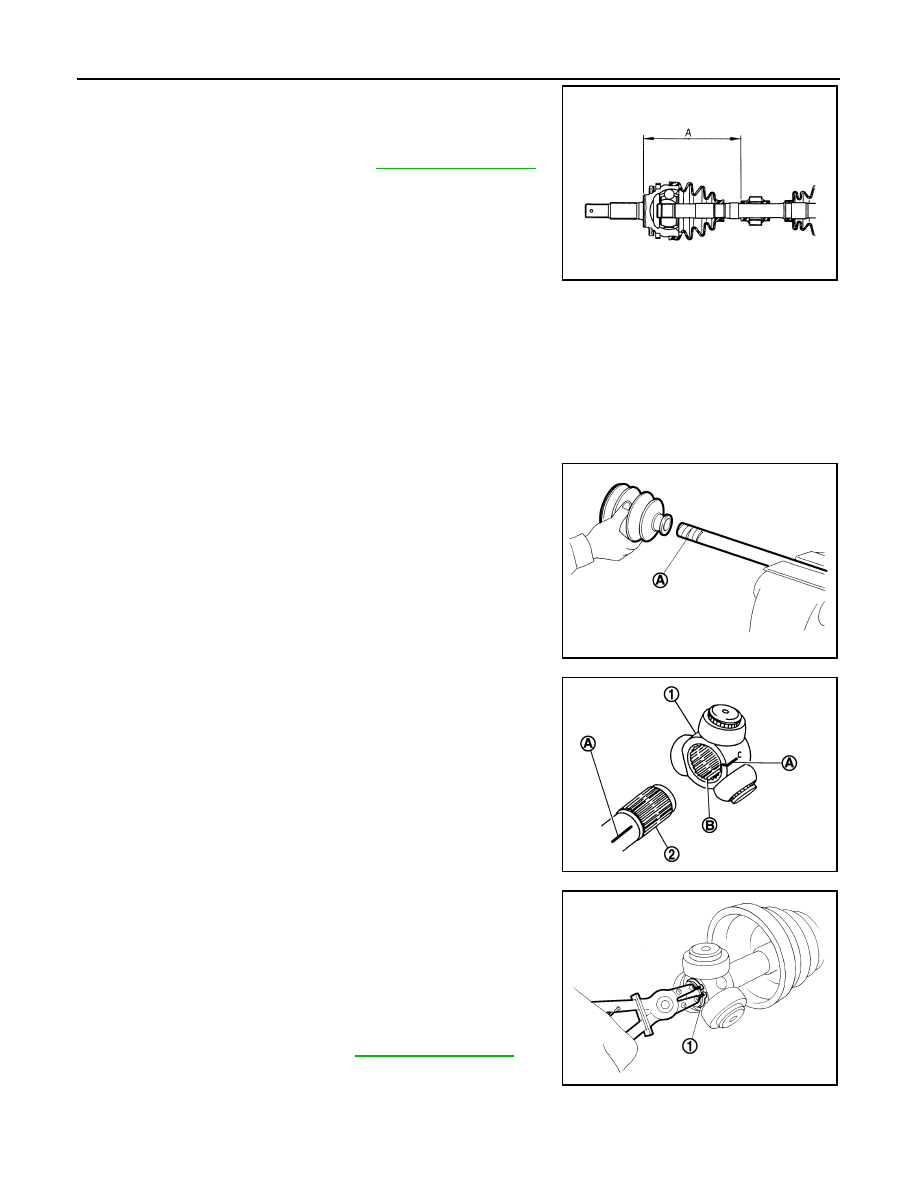
5. Install new boot and boot bands to shaft.

CAUTION:

• Wrap serration on shaft with tape (A) to protect boot from

damage.

• Do not reuse boot and boot bands. 

6. Remove the tape wrapped around the serration on shaft.

7. To install the spider assembly (1), align it with the matching

marks (A) on the shaft (2) during the removal, and direct the ser-

ration mounting surface (B) to the shaft.

8. Secure spider assembly onto shaft with snap ring (1).

CAUTION:

Do not reuse snap ring.

9. Apply the appropriate amount of grease to spider assembly and

sliding surface.

10. Assemble the housing onto spider assembly, and apply the bal-

ance of the specified amount grease.

11. Align matching marks put during the removal of housing.

12. Install boot securely into grooves (indicated by “*” marks).

CAUTION:

Dimension (A) 

: Refer to 

FAX-24, "Drive Shaft"

.

JPDIF0178ZZ

JPDIF0009ZZ

JPDIF0017ZZ

Grease quantity

: Refer to 

FAX-24, "Drive Shaft"

.

JPDIF0014ZZ

FRONT DRIVE SHAFT

FAX-21

< UNIT DISASSEMBLY AND ASSEMBLY >

C

E

F

G

H

I

J

K

L

M

A

B

FAX

N

O

P

If grease adheres to the boot mounting surface (with “*” mark) on shaft or housing, boot may be

removed. Remove all grease from the surface.

13. To prevent the deformation of the boot, adjust the boot installa-

tion length to the value shown below by inserting the suitable

tool into the inside of boot from the large diameter side of boot

and discharging inside air.

CAUTION:

• If the boot installation length exceeds the standard, it may

cause breakage of the boot.

• Be careful not to touch the inside of the boot with the tip

of tool.

14. Install large and smaller boot bands securely.

CAUTION:

Do not reuse boot bands.

a. Put boot band in the groove on drive shaft boot. Then fit pawls

into holes to temporary installation.

: Pawl

NOTE:

For the large diameter side, fit projection (A) and guide slit (B) at

first.

b. Pinch projection on the band with suitable pliers to tighten band.

c. Insert the tip of band into the lower part of pawl as shown.

: Pawl

15. Check that displacement does not occur when boot is rotated

with the housing assembly fixed.

CAUTION:

• If displacement occurs, replace band.

• Do not reuse boot band.

Wheel Side

1. Clean the old grease on joint sub-assembly with paper waste.
2. Fill serration slot joint sub-assembly (1) with NISSAN genuine

grease or equivalent until the serration slot and ball groove

become full to the brim.

CAUTION:

After applying grease, use a paper waste to wipe off old

grease that has oozed out.

3. Install boot and boot bands to shaft.

CAUTION:

Boot installation 
length (L)

: Refer to 

FAX-24, "Drive Shaft"

.

JPDIF0230ZZ

JPDIF0157ZZ

JPDIF0158ZZ

JPDIF0008ZZ

FAX-22

< UNIT DISASSEMBLY AND ASSEMBLY >

FRONT DRIVE SHAFT

• Wrap serration on shaft with tape (A) to protect the boot

from damage.

• Do not reuse boot and boot band.

4. Remove the tape wrapped around the serration on shaft.

5. Position the circlip (1) on groove at the shaft edge.

CAUTION:

Do not reuse circlip.

NOTE:

Drive joint inserter is recommended when installing circular clip.

6. Align both center axles of the shaft edge and joint sub-assembly.

Then assemble shaft with joint sub-assembly holding circular

clip.

7. Install joint sub-assembly to shaft using plastic hammer.

CAUTION:

• Check circlip is properly positioned on groove of the joint

sub-assembly.

• Confirm that joint sub-assembly is correctly engaged

while rotating drive shaft.

8. Apply the specified amount of grease into the boot inside from

large diameter side of boot.

9. Install the boot securely into grooves (indicated by “*” marks).

CAUTION:

If grease adheres to the boot mounting surface (indicated by “*” mark) on the shaft or joint sub-

assembly, boot may be removed. Remove all grease from the boot mounting surface.

10. To prevent the deformation of the boot, adjust the boot installa-

tion length to the specified value shown below by inserting the

suitable tool into inside of the boot from the large diameter side

of the boot and discharging the inside air.

CAUTION:

• If the boot installation length exceeds the standard, it may

cause breakage of the boot.

• Be careful not to touch the inside of the boot with a tip of

tool.

JPDIF0009ZZ

JPDIF0305ZZ

Grease quantity

: Refer to 

FAX-24, "Drive Shaft"

.

RAC0049D

Boot installation 
length (L)

: Refer to 

FAX-24, "Drive Shaft"

.

JPDIG0136ZZ

FRONT DRIVE SHAFT

FAX-23

< UNIT DISASSEMBLY AND ASSEMBLY >

C

E

F

G

H

I

J

K

L

M

A

B

FAX

N

O

P

11. Secure the large and small ends of the boot with boot bands

using Tool (A).

CAUTION:

• Do not reuse boot band.

• Secure boot band so that dimension (M) meets the speci-

fication as shown.

12. Check that displacement does not occur when boot is rotated

with the joint sub-assembly and shaft.

CAUTION:

Do not reuse boot band.

Tool number : KV40107300 ( — )

JPDIF0012ZZ

Dimension (M)

: Refer to 

FAX-25, "Boot Bands"

.

AWDIA0598ZZ


Content   ..  440  441  442  443   ..