Nissan Versa Sedan. Instruction - part 426
FRONT FOG LAMP
EXL-105
< REMOVAL AND INSTALLATION >
C
D
E
F
G
H
I
J
K
M
A
B
EXL
N
O
P
FRONT FOG LAMP
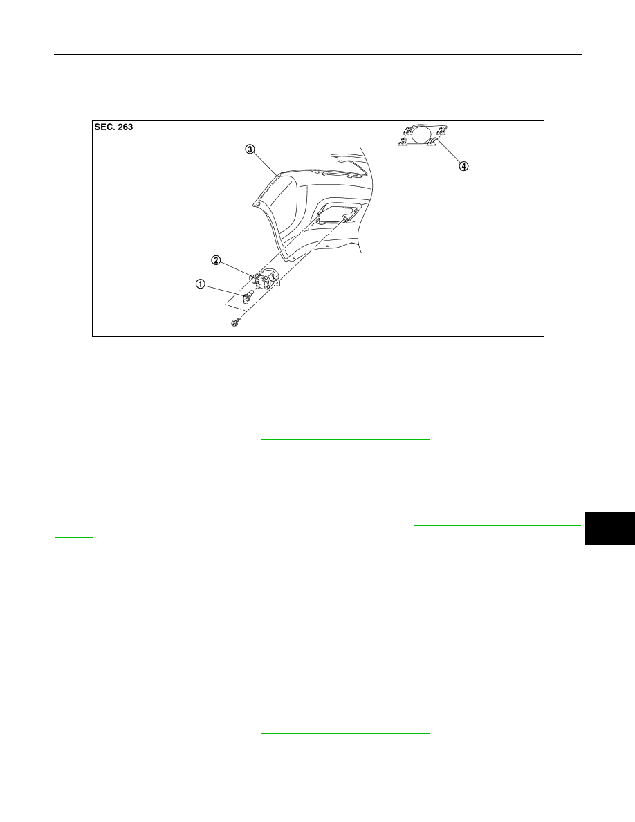
Exploded View
INFOID:0000000009269673
Removal and Installation
INFOID:0000000009269674
REMOVAL
1. Remove the fender protector. Refer to
EXT-26, "Removal and Installation"
2. Disconnect the harness connector from the front fog lamp.
3. Remove the screws and front fog lamp.
INSTALLATION
Installation is in the reverse order of removal.
NOTE:
After installation, perform fog lamp aiming adjustment procedure. Refer to
EXL-101, "Aiming Adjustment Pro-
Bulb Replacement
INFOID:0000000009269675
WARNING:
Do not touch bulb with your hand while it is on or right after being turned off. Burning may result.
CAUTION:
• Disconnect the battery negative terminal or remove power circuit fuse while performing the opera-
tion.
• Do not touch the glass surface of the bulb with bare hands or allow oil or grease to get on it to pre-
vent damage to the bulb.
• Do not leave bulb out of lamp reflector for a long time because dust, moisture smoke, etc. may affect
the performance of lamp. When replacing bulb, be sure to replace it with new one.
FRONT FOG LAMP BULB
Removal
1. Remove the fender protector. Refer to
EXT-26, "Removal and Installation"
1.
Front fog lamp bulb
2.
Front fog lamp
3.
Front bumper fascia
4.
Front fog lamp finisher
JMLIA2043ZZ