Nissan Versa Sedan. Instruction - part 386
CYLINDER HEAD
EM-79
< REMOVAL AND INSTALLATION >
[HR16DE]
C
D
E
F
G
H
I
J
K
L
M
A
EM
N
P
O
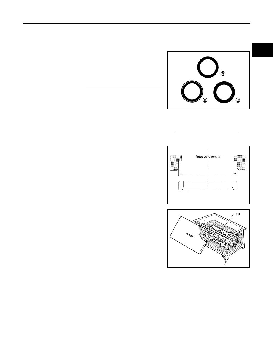
VALVE SEAT CONTACT
• After confirming that the dimensions of valve guides and valves are within the specifications, perform this
procedure.
• Apply prussian blue (or white lead) onto contacting surface of valve seat to check the condition of the valve
contact on the surface.
• Check if the contact area band is continuous all around the circum-
ference.
• If not, grind to adjust valve fitting and check again. If the contacting
surface still has “NG” conditions (B) even after the recheck,
replace valve seat. Refer to
EM-75, "Disassembly and Assembly"
.
VALVE SEAT REPLACEMENT
When valve seat is removed, replace with oversized [0.5 mm (0.020 in)] valve seat.
1. Bore out old seat until it collapses. Boring should not continue beyond the bottom face of the seat recess
in cylinder head. Set the machine depth stop to ensure this. Refer to
MA-12, "Fluids and Lubricants"
.
CAUTION:
Prevent scoring cylinder head by excessive boring.
2. Ream cylinder head recess diameter for service valve seat.
• Be sure to ream in circles concentric to the valve guide center.
This will enable valve seat to fit correctly.
3. Heat cylinder head to 110 to 130
°C (230 to 266°F) by soaking in
heated oil.
4. Provide valve seats cooled well with dry ice. Press-fit valve seats into cylinder head.
WARNING:
Cylinder head contains heat; when working, wear protective equipment to avoid getting burned.
CAUTION:
Avoid directly touching cold valve seats.
(A)
: OK
JPBIA0187ZZ
Oversize [0.5 mm (0.020 in)]
Intake
: 32.500 - 32.527 mm (1.2795 - 1.2805 in)
Exhaust
: 26.400 - 26.427 mm (1.0393 - 1.0404 in)
SEM795A
SEM008A