Nissan Versa Sedan. Instruction - part 375


  Index      Nissan     Nissan Versa Sedan (2014 year) - Service and Repair Instruction


Search            copyright infringement  


Content   ..  373  374  375  376   ..


Nissan Versa Sedan. Instruction - part 375


OIL PAN (LOWER)

EM-35

< REMOVAL AND INSTALLATION >

[HR16DE]

C

D

E

F

G

H

I

J

K

L

M

A

EM

N

P

O

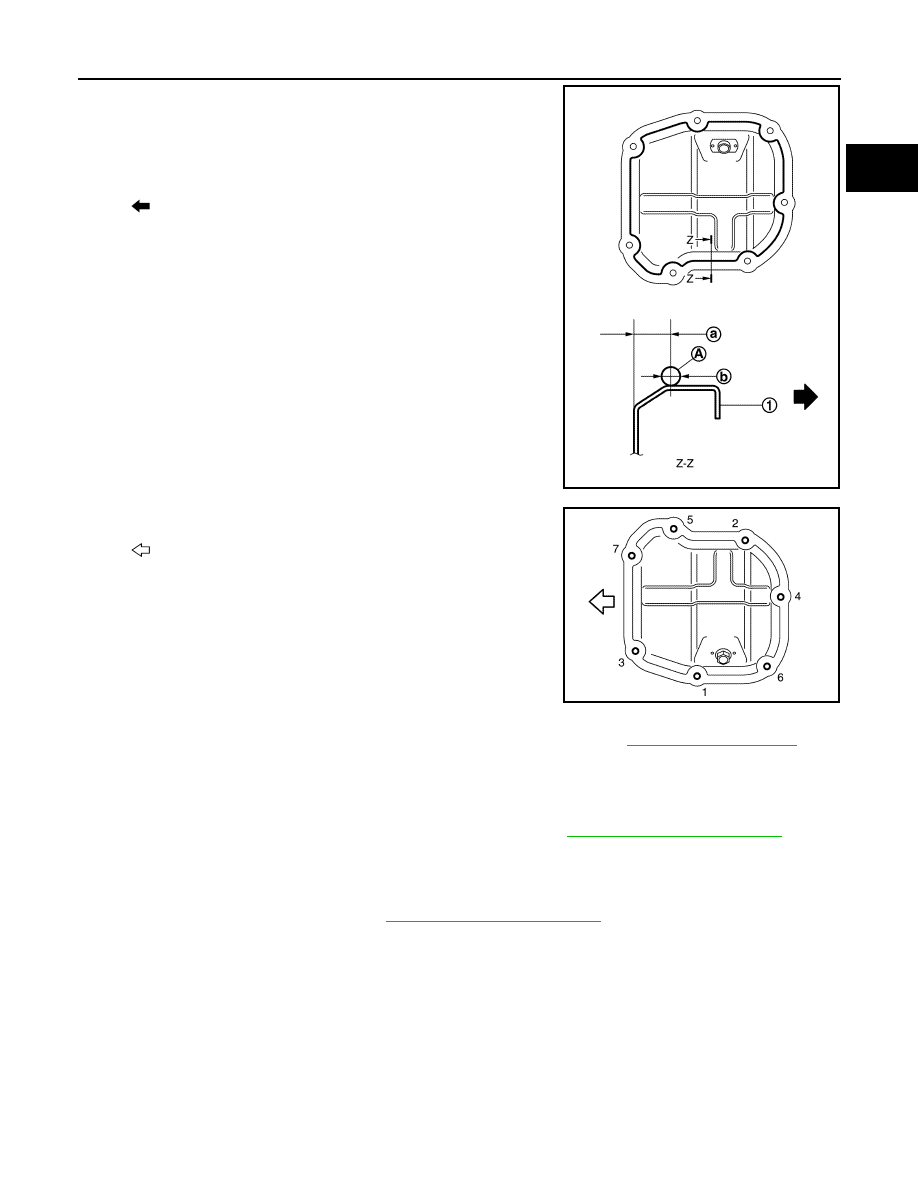
2. Apply a continuous bead of liquid gasket (A) with a tube presser

as shown. 

Use Genuine Silicone RTV Sealant or equivalent.

CAUTION:

• The components must be installed within 5 minutes of the

liquid gasket application.

• Do not confirm torque after the 5 minutes have elapsed.

• Then allow 30 minutes for the liquid gasket to set before

adding oil to the engine.

3. Tighten bolts in numerical order as shown. 

4. Install oil pan drain plug.

• Refer to the figure for installation direction of drain plug washer. Refer to 

EM-33, "Exploded View"

.

CAUTION:

• Installation should be done within 5 minutes after applying liquid gasket.

• Do not fill the engine with oil for at least 30 minutes after the oil pan (lower) is installed to allow

the sealant to cure.

5. Add the specified oil after waiting for at least 30 minutes. Refer to 

MA-12, "Fluids and Lubricants"

.

INSPECTION AFTER INSTALLATION

• Before starting engine, check oil/fluid levels, including engine coolant and engine oil. If less than required

quantity, fill to the specified level. Refer to 

MA-12, "Fluids and Lubricants"

.

• Use procedure below to check for fuel leakage.

• Turn ignition switch ON (with engine stopped). With fuel pressure applied to fuel piping, check for fuel leak-

age at connection points.

• Start engine. With engine speed increased, check again for fuel leakage at connection points.

• Run engine to check for unusual noise and vibration.

NOTE:

If hydraulic pressure inside timing chain tensioner drops after removal and installation, slack in the guide

may generate a pounding noise during and just after engine start. However, this is normal. Noise will stop

after hydraulic pressure rises.

• Warm up engine thoroughly to make sure there is no leakage of fuel, exhaust gas, or any oils/fluids including

engine oil and engine coolant.

• Bleed air from passages in lines and hoses, such as in cooling system.

(1)

: Oil pan (lower)

(a)

: 7.5 - 9.5 mm (0.295 - 0.374 in)

(b)

: 4.0 - 5.0 mm (0.157 - 0.197 in) diameter

: Engine outside

JSBIA1128ZZ

: Engine front

JSBIA1126ZZ

EM-36

< REMOVAL AND INSTALLATION >

[HR16DE]

OIL PAN (LOWER)

• After cooling down engine, again check oil/fluid levels including engine oil and engine coolant. Refill to spec-

ified level, if necessary.

• Summary of the inspection items:

*Power steering fluid, brake fluid, etc.

Item

Before starting engine

Engine running

After engine stopped

Engine coolant

Level

Leakage

Level

Engine oil

Level

Leakage

Level

Transmission/
transaxle fluid 

A/T and CVT Models

Leakage

Level/Leakage

Leakage

M/T Models

Level/Leakage

Leakage

Level/Leakage

Other oils and fluids*

Level

Leakage

Level

Fuel

Leakage

Leakage

Leakage

Exhaust gas

Leakage

FUEL INJECTOR AND FUEL TUBE

EM-37

< REMOVAL AND INSTALLATION >

[HR16DE]

C

D

E

F

G

H

I

J

K

L

M

A

EM

N

P

O

FUEL INJECTOR AND FUEL TUBE

Exploded View

INFOID:0000000009266653

CAUTION:

Do not remove or disassemble parts unless instructed. 

Removal and Installation

INFOID:0000000009266654

WARNING:

• Put a “CAUTION: FLAMMABLE” sign in the workshop.

• Be sure to work in a well-ventilated area and furnish workshop with a CO

2

 fire extinguisher. 

• Do not smoke while servicing fuel system. Keep open flames and sparks away from the work area.

REMOVAL

1. Release the fuel pressure. Refer to 

EC-133, "Work Procedure"

.

2. Remove intake manifold. Refer to 

EM-27, "Removal and Installation"

.

1.

Stud bolt

2.

O-ring (green)

3.

Fuel injector (front)

4.

Clip

5.

Fuel injector (rear)

6.

O-ring (black)

7.

Fuel tube protector

8.

Fuel tube

9.

Clamp

10. Quick connector cap (engine side)

11. Fuel feed hose

12. Quick connector cap (floor piping-side)

13. Fuel connector protector

14. Fuel pipe

A.

To centralized under-floor piping

AWBIA1473ZZ

EM-38

< REMOVAL AND INSTALLATION >

[HR16DE]

FUEL INJECTOR AND FUEL TUBE

3. Disconnect fuel feed hose from fuel tube. Disconnect quick con-

nector:

NOTE:

There is no fuel return path.

a. Remove quick connector cap (engine side) (1) from quick con-

nector connection.

b. Disconnect fuel feed hose from hose clamp.

c.

With the sleeve (B) side of quick connector release (A) facing

quick connector (2), install quick connector release (A) onto fuel

tube (1) as shown.

d. Insert quick connector release (A) into quick connector (2) until

sleeve (B) contacts and goes no further. Hold quick connector

release (A) in that position (D).

CAUTION:

Inserting quick connector release hard will not disconnect

quick connector. Hold quick connector release where it

contacts and goes no further.

e. Draw and pull out quick connector (E) straight up from fuel tube

(1).

CAUTION:

• Pull quick connector up (E) from holding position (C) as shown. 

• Do not pull with lateral force applied. O-ring inside quick connector may be damaged.

• Prepare container and cloth beforehand as fuel will leak out.

• Do not reuse O-ring.

• Avoid fire and sparks.

• Keep parts away from heat source. Be especially careful when welding is performed. 

• Do not expose parts to battery electrolyte or other acids.

• Do not bend or twist connection between quick connector and fuel feed tube during installation

or removal.

• Be sure to cover openings of disconnected fuel feed hose

(A) and fuel tube (C) with plug or plastic bag (B) to avoid

fuel leaks and entry of foreign material.

4. Disconnect fuel feed hose from fuel pipe as follows:

(1)

: Quick connector cap (engine side)

JPBIA4130ZZ

JPBIA4131ZZ

JPBIA2255ZZ

JSBIA1295ZZ


Content   ..  373  374  375  376   ..