Nissan Versa Sedan. Instruction - part 373
INTAKE MANIFOLD
EM-27
< REMOVAL AND INSTALLATION >
[HR16DE]
C
D
E
F
G
H
I
J
K
L
M
A
EM
N
P
O
INTAKE MANIFOLD
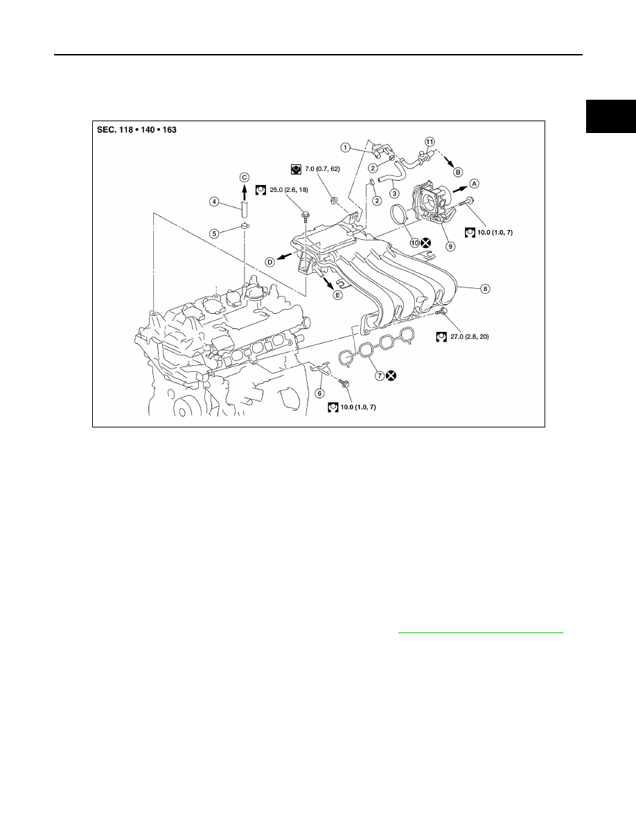
Exploded View
INFOID:0000000009266647
Removal and Installation
INFOID:0000000009266648
REMOVAL
NOTE:
When removing components such as hoses, tubes/lines, etc., cap or plug openings to prevent fluid from spill-
ing.
1. Remove air duct (inlet), air duct and air cleaner assembly. Refer to
EM-25, "Removal and Installation"
2. Disconnect water hoses from electric throttle control actuator.
CAUTION:
• Perform this step when the engine is cold.
• Do not spill engine coolant on drive belt.
3. Remove electric throttle control actuator.
CAUTION:
• Handle carefully to avoid any shock to electric throttle control actuator.
• Do not disassemble electric throttle control actuator.
4. Disconnect harness connector and vacuum hose from EVAP purge control solenoid valve.
CAUTION:
Handle EVAP canister purge volume control solenoid valve carefully and avoid impacts.
5. Disconnect vacuum hose for brake booster from intake manifold.
1.
EVAP canister purge volume control
solenoid valve
2.
Hose clamp
3.
Vacuum hose
4.
PCV hose
5.
Hose clamp
6.
Intake manifold support
7.
Gasket
8.
Intake manifold
9.
Electric throttle control actuator
10. Gasket
11. EVAP service port
A.
To air duct
B.
To centralized under-floor piping
C.
To brake booster
D.
To air duct
E.
To rocker cover
AWBIA1471ZZ