Nissan Versa Sedan. Instruction - part 357


  Index      Nissan     Nissan Versa Sedan (2014 year) - Service and Repair Instruction


Search            copyright infringement  


Content   ..  355  356  357  358   ..


Nissan Versa Sedan. Instruction - part 357


COOLING FAN

EC-427

< DTC/CIRCUIT DIAGNOSIS >

[HR16DE]

C

D

E

F

G

H

I

J

K

L

M

A

EC

N

P

O

YES

>> Replace IPDM E/R. Refer to 

PCS-30, "Removal and Installation"

 (WITH I-KEY) or 

PCS-56,

"Removal and Installation"

 (WITHOUT I-KEY).

NO 

>> Repair or replace harness or connector.

EXCEPT FOR SINGLE CONNECTOR COOLING FAN WITHOUT A/C MODELS

1.

CHECK COOLING FAN MOTOR CIRCUIT

1. Disconnect cooling fan motor harness connector.

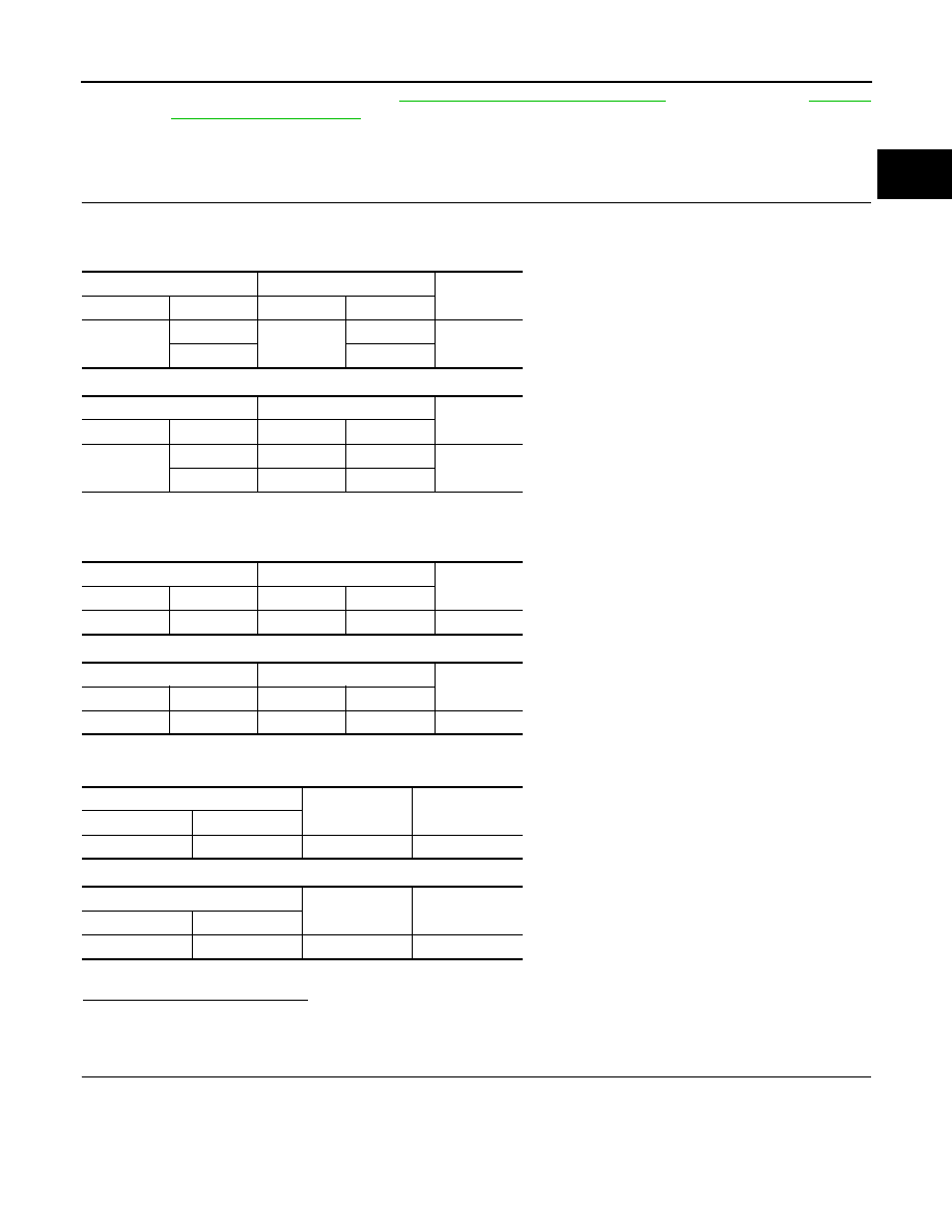
2. Check the continuity between IPDM E/R harness connector and cooling fan motor harness connector.

For single connector cooling fan with A/C

For Dual connector cooling fan

3. Check the continuity between cooling fan relay harness connector and cooling fan motor harness connec-

tor.

For single connector cooling fan with A/C models

For Dual connector cooling fan models

4. Check the continuity between cooling fan motor harness connector and ground.

For single connector cooling fan with A/C models

For Dual connector cooling fan models

5. Also check harness for short to ground and short to power.
Is the inspection result normal?

YES

>> GO TO 2.

NO

>> Repair open circuit or short to ground or short to power in harness or connectors.

2.

CHECK COOLING FAN RELAY CIRCUIT

1. Disconnect cooling fan relay harness connector.

2. Disconnect IPDM E/R harness connector.

3. Check the continuity between IPDM E/R harness connector and cooling fan relay harness connector.

IPDM E/R

Cooling fan motor

Continuity

Connector

Terminal

Connector

Terminal

E43

7

E31

2

Existed

5

1

IPDM E/R

Cooling fan motor

Continuity

Connector

Terminal

Connector

Terminal

E43

7

E5

1

Existed

5

E32

3

Cooling fan relay

Cooling fan motor

Continuity

Connector

Terminal

Connector

Terminal

E62

5

E31

4

Existed

Cooling fan relay

Cooling fan motor

Continuity

Connector

Terminal

Connector

Terminal

E62

5

E32

4

Existed

Cooling fan motor

Ground

Continuity

Connector

Terminal

E31

3

Ground

Existed

Cooling fan motor

Ground

Continuity

Connector

Terminal

E5

2

Ground

Existed

EC-428

< DTC/CIRCUIT DIAGNOSIS >

[HR16DE]

COOLING FAN

4. Check the continuity between cooling fan relay harness connector and ground.

5. Also check harness for short to ground and short to power.
Is the inspection result normal?

YES

>> GO TO 3.

NO

>> Repair open circuit or short to ground or short to power in harness or connectors.

3.

CHECK COOLING FAN RELAY

Refer to 

EC-429, "Component Inspection (Cooling Fan Relay)"

.

YES or NO

YES

>> GO TO 4.

NO

>> Replace cooling fan relay.

4.

CHECK COOLING FAN MOTOR

Refer to 

EC-428, "Component Inspection (Cooling Fan Motor)"

.

YES or NO

YES

>> GO TO 5.

NO

>> Replace cooling fan motor. Refer to 

CO-17, "Removal and Installation"

.

5.

CHECK INTERMITTENT INCIDENT

Perform 

GI-45, "Intermittent Incident"

.

YES or NO

YES

>> Replace IPDM E/R. Refer to 

PCS-30, "Removal and Installation"

 (WITH I-KEY) or 

PCS-56,

"Removal and Installation"

 (WITHOUT I-KEY).

NO 

>> Repair or replace harness or connector.

Component Inspection (Cooling Fan Motor)

INFOID:0000000009267302

1.

CHECK COOLING FAN MOTOR

1. Turn ignition switch OFF.

2. Disconnect cooling fan motor harness connector.

3. Supply cooling fan motor terminals with battery voltage and check operation.

For single connector cooling fan without A/C models

IPDM E/R

Cooling fan relay

Continuity

Connector

Terminal

Connector

Terminal

E46

65

E62

1

Existed

59

2

Cooling fan relay

Ground

Continuity

Connector

Terminal

E62

3

Ground

Existed

Cooling fan motor

Operation

Connector

+

terminals

E3

1

3

Cooling fan motor operates

2

4

COOLING FAN

EC-429

< DTC/CIRCUIT DIAGNOSIS >

[HR16DE]

C

D

E

F

G

H

I

J

K

L

M

A

EC

N

P

O

For single connector cooling fan with A/C models

For Dual connector cooling fan models

Is the inspection result normal?

YES

>> INSPECTION END

NO

>> Replace cooling fan motor. Refer to 

CO-17, "Removal and Installation"

.

Component Inspection (Cooling Fan Relay)

INFOID:0000000009267303

1.

CHECK COOLING FAN RELAY

1. Turn ignition switch OFF.

2. Remove cooling fan relay.

3. Check continuity between cooling fan relay terminals under the

following conditions.

Is the inspection result normal?

YES

>> INSPECTION END

NO

>> Replace cooling fan relay.

Cooling fan motor

Operation

Connector

+

terminals

E31

2

3

Cooling fan motor operates

1

4

Cooling fan motor

Operation

Connector

+

terminals

E5

1

2

Cooling fan motor operates

E32

3

4

Cooling fan relay

Conditions

Continuity

terminals

3

5

12 V direct current supply between 
terminals 1 and 2

Existed

No current supply

Not existed

JSBIA0671ZZ

EC-430

< DTC/CIRCUIT DIAGNOSIS >

[HR16DE]

ELECTRICAL LOAD SIGNAL

ELECTRICAL LOAD SIGNAL

Description

INFOID:0000000009267304

The electrical load signal (Headlamp switch signal, rear window defogger switch signal, etc.) is transferred to

ECM through the CAN communication line.

Component Function Check

INFOID:0000000009267305

1.

CHECK REAR WINDOW DEFOGGER SWITCH FUNCTION

1. Turn ignition switch ON.

2. Select “DATA MONITOR” mode with CONSULT.

3. Select “LOAD SIGNAL” and check indication under the following conditions.

Is the inspection result normal?

YES

>> GO TO 2.

NO

>> Go to 

EC-430, "Diagnosis Procedure"

.

2.

CHECK LIGHTING SWITCH FUNCTION

Check “LOAD SIGNAL” indication under the following conditions.

Is the inspection result normal?

YES

>> GO TO 3.

NO

>> Go to 

EC-430, "Diagnosis Procedure"

.

3.

CHECK HEATER FAN CONTROL SWITCH FUNCTION

Select “HEATER FAN SW” and check indication under the following conditions.

Is the inspection result normal?

YES

>> INSPECTION END

NO

>> Go to 

EC-430, "Diagnosis Procedure"

.

Diagnosis Procedure

INFOID:0000000009267306

1.

INSPECTION START

Confirm the malfunctioning circuit (rear window defogger, headlamp or heater fan). Refer to 

EC-430, "Compo-

nent Function Check"

.

Which circuit is related to the incident?

Rear window defogger>>GO TO 2

Headlamp>>GO TO 3.

Heater fan>>GO TO 4.

2.

CHECK REAR WINDOW DEFOGGER SYSTEM

Perform trouble diagnosis of rear window defogger system. Refer to 

DEF-16, "Work Flow"

.

Monitor item

Condition

Indication

LOAD SIGNAL Rear window defogger switch

ON

ON

OFF

OFF

Monitor item

Condition

Indication

LOAD SIGNAL Lighting switch

ON at 2nd position

ON

OFF

OFF

Monitor item

Condition

Indication

HEATER FAN SW Heater fan control switch

ON

ON

OFF

OFF


Content   ..  355  356  357  358   ..