Nissan Versa Sedan. Instruction - part 312
P0172 FUEL INJECTION SYSTEM FUNCTION
EC-247
< DTC/CIRCUIT DIAGNOSIS >
[HR16DE]
C
D
E
F
G
H
I
J
K
L
M
A
EC
N
P
O
6. Also check harness for short to power.
Is the inspection result normal?
YES
>> GO TO 4.
NO
>> Repair open circuit or short to ground or short to power in harness or connectors.
4.
CHECK FUEL PRESSURE
1. Release fuel pressure to zero. Refer to
.
2. Install fuel pressure gauge and check fuel pressure. Refer to
.
Is the inspection result normal?
YES
>> GO TO 6.
NO
>> GO TO 5.
5.
CHECK FUEL HOSES AND FUEL TUBES
Check fuel hoses and fuel tubes for clogging.
Is the inspection result normal?
YES
>> Replace “fuel filter and fuel pump assembly”. Refer to
.
NO
>> Repair or replace
6.
CHECK MASS AIR FLOW SENSOR
With CONSULT
1. Install all removed parts.
2. Check “MASS AIRFLOW” in “DATA MONITOR” mode with CONSULT.
With GST
1. Install all removed parts.
2. Check mass air flow sensor signal in Service $01 with GST.
Is the measurement value within the specification?
YES
>> GO TO 7.
NO
>> Check connectors for rusted terminals or loose connections in the mass air flow sensor circuit or
grounds. Refer to
.
7.
CHECK FUNCTION OF FUEL INJECTOR
With CONSULT
1. Start engine.
2. Perform “POWER BALANCE” in “ACTIVE TEST” mode with CONSULT.
3. Make sure that each circuit produces a momentary engine speed drop.
Without CONSULT
1. Let engine idle.
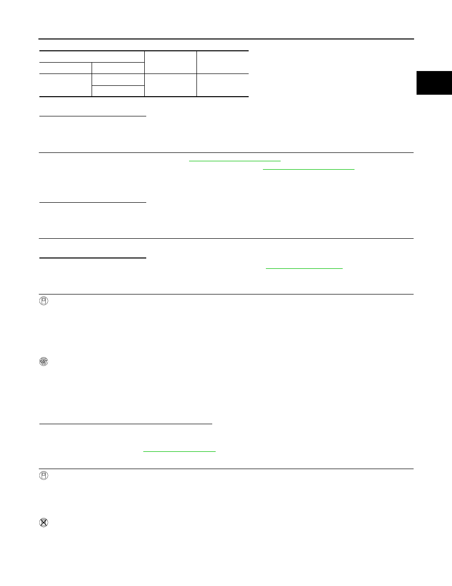
ECM
Ground
Continuity
Connector
Terminal
F11
49
Ground
Not existed
53
At idling: Approximately 350 kPa (3.57 kg/cm
2
, 51 psi)
0.8 - 4.0 g/s
: at idling
2.0 - 10.0 g/s : at 2,500 rpm
0.8 - 4.0 g/s
: at idling
2.0 - 10.0 g/s : at 2,500 rpm