Nissan Versa Sedan. Instruction - part 258


  Index      Nissan     Nissan Versa Sedan (2014 year) - Service and Repair Instruction


Search            copyright infringement  


Content   ..  256  257  258  259   ..


Nissan Versa Sedan. Instruction - part 258


SYSTEM

EC-31

< SYSTEM DESCRIPTION >

[HR16DE]

C

D

E

F

G

H

I

J

K

L

M

A

EC

N

P

O

ENGINE CONTROL SYSTEM : System Description

INFOID:0000000009266989

ECM performs various controls such as fuel injection control and ignition timing control.

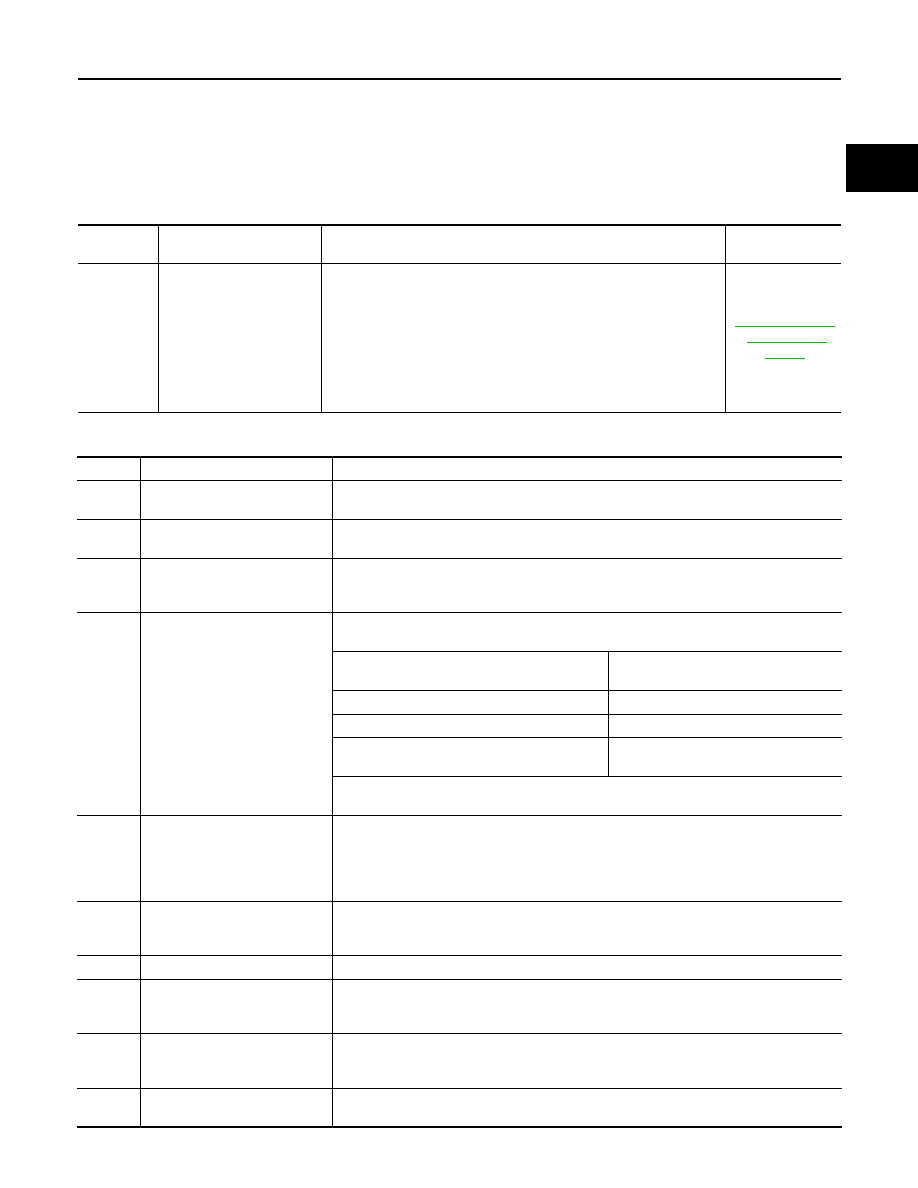
ENGINE CONTROL SYSTEM : Fail Safe

INFOID:0000000009619854

NON DTC RELATED ITEM

DTC RELATED ITEM

Detected 

items

Engine operating condition 

in fail-safe mode

Remarks

Reference page

Malfunction 
indicator 
lamp  circuit

Engine speed will not rise 
more than 2,500 rpm due 
to the fuel cut

When there is an open circuit on MIL circuit, the ECM cannot warn the 
driver by lighting up MIL when there is malfunction on engine control 
system.
Therefore, when electrical controlled throttle and part of ECM related 
diagnoses are continuously detected as NG for 5 trips, ECM warns the 
driver that engine control system malfunctions and MIL circuit is open 
by means of operating fail safe function.
The fail safe function also operates when above diagnoses except MIL 
circuit are detected and demands the driver to repair the malfunction.

EC-442, "Compo-

nent Function 

Check"

DTC No.

Detected items

Engine operating condition in fail safe mode

P0011

Intake valve timing control

The signal is not energized to the intake valve timing control solenoid valve and the valve 
control does not function.

P0014

Exhaust valve timing control

The signal is not energized to the exhaust valve timing control solenoid valve and the valve 
control does not function.

P0101
P0102
P0103

Mass air flow sensor circuit

Engine speed will not rise more than 2,400 rpm due to the fuel cut.

P0117
P0118

Engine coolant temperature 
sensor circuit

Engine coolant temperature will be determined by ECM based on the following conditions.
CONSULT displays the engine coolant temperature decided by ECM.

Condition

Engine coolant temperature decided 

(CONSULT display)

Just as ignition switch is turned ON or START

40

°C (104°F)

Approx. 4 minutes or more after engine starting

80

°C (176°F)

Except as shown above

40 - 80

°C (104 - 176°F)

(Depends on the time)

When the fail safe system for engine coolant temperature sensor is activated, the cooling 
fan operates while engine is running.

P0122
P0123
P0222
P0223
P2135

Throttle position sensor

The ECM controls the electric throttle control actuator in regulating the throttle opening in 
order for the idle position to be within +10 degrees.
The ECM regulates the opening speed of the throttle valve to be slower than the normal 
condition.
So, the acceleration will be poor. 

P0196
P0197
P0198

Engine oil temperature sensor

Exhaust valve timing control does not function.

P0500

Vehicle speed sensor

The cooling fan operates (Highest) while engine is running.

P0524

Engine oil pressure

• ECM illuminates oil pressure warning lamp on the combination meter.
• Engine speed will not rise more than 4,000 rpm due to the fuel cut.
• Fail-safe is canceled when ignition switch OFF 

→ ON.

P0605

ECM

(When ECM calculation function is malfunctioning:)
ECM stops the electric throttle control actuator control, throttle valve is maintained at a 
fixed opening (approx. 5 degrees) by the return spring.

P0643

Sensor power supply

ECM stops the electric throttle control actuator control, throttle valve is maintained at a 
fixed opening (approx. 5 degrees) by the return spring.

EC-32

< SYSTEM DESCRIPTION >

[HR16DE]

SYSTEM

MULTIPORT FUEL INJECTION SYSTEM

P1805

Brake switch

ECM controls the electric throttle control actuator by regulating the throttle opening to a 
small range.
Therefore, acceleration will be poor.

Vehicle condition

Driving condition

When engine is idling

Normal

When accelerating

Poor acceleration

P2100
P2103

Throttle control motor relay

ECM stops the electric throttle control actuator control, throttle valve is maintained at a 
fixed opening (approx. 5 degrees) by the return spring.

P2101

Electric throttle control function

ECM stops the electric throttle control actuator control, throttle valve is maintained at a 
fixed opening (approx. 5 degrees) by the return spring.

P2118

Throttle control motor

ECM stops the electric throttle control actuator control, throttle valve is maintained at a 
fixed opening (approx. 5 degrees) by the return spring.

P2119

Electric throttle control actuator

(When electric throttle control actuator does not function properly due to the return spring 
malfunction:)
ECM controls the electric throttle actuator by regulating the throttle opening around the 
idle position. The engine speed will not rise more than 2,000 rpm.

(When throttle valve opening angle in fail safe mode is not in specified range:)
ECM controls the electric throttle control actuator by regulating the throttle opening to 20 
degrees or less.

(When ECM detects the throttle valve is stuck open:)
While the vehicle is driving, it slows down gradually by fuel cut. After the vehicle stops, the 
engine stalls.
The engine can restart in the Neutral position, and engine speed will not exceed 1,000 rpm 
or more.

P2122
P2123
P2127
P2128
P2138

Accelerator pedal position sen-
sor

The ECM controls the electric throttle control actuator in regulating the throttle opening in 
order for the idle position to be within +10 degrees.
The ECM regulates the opening speed of the throttle valve to be slower than the normal 
condition.
So, the acceleration will be poor. 

DTC No.

Detected items

Engine operating condition in fail safe mode

SYSTEM

EC-33

< SYSTEM DESCRIPTION >

[HR16DE]

C

D

E

F

G

H

I

J

K

L

M

A

EC

N

P

O

MULTIPORT FUEL INJECTION SYSTEM : System Diagram

INFOID:0000000009266990

MULTIPORT FUEL INJECTION SYSTEM : System Description

INFOID:0000000009266991

INPUT/OUTPUT SIGNAL CHART

JPBIA4882GB

EC-34

< SYSTEM DESCRIPTION >

[HR16DE]

SYSTEM

*1: M/T models

*2: A/T models or CVT models

*3: This sensor is not used to control the engine system under normal conditions.

*4: ECM determines the start signal status by the signals of engine speed and battery voltage.

*5: This signal is sent to the ECM through CAN communication line.

SYSTEM DESCRIPTION

The amount of fuel injected from the fuel injector is determined by the ECM. The ECM controls the length of

time the valve remains open (injection pulse duration). The amount of fuel injected is a program value in the

ECM memory. The program value is preset by engine operating conditions. These conditions are determined

by input signals (for engine speed and intake air) from the crankshaft position sensor, camshaft position sen-

sor and the mass air flow sensor.

VARIOUS FUEL INJECTION INCREASE/DECREASE COMPENSATION

In addition, the amount of fuel injected is compensated to improve engine performance under various operat-

ing conditions as listed below.

<Fuel increase>

• During warm-up

• When starting the engine

• During acceleration

• Hot-engine operation

• When selector lever position is changed from N to D (A/T models or CVT models)

• High-load, high-speed operation

<Fuel decrease>

• During deceleration

• During high engine speed operation

Sensor

Input signal to ECM

ECM function

Actuator

Crankshaft position sensor (POS)

Engine speed

*4

Piston position

Fuel injection & mixture 
ratio control

Fuel injector

Camshaft position sensor (PHASE)

Mass air flow sensor

Amount of intake air

Intake air temperature sensor

Intake air temperature

Engine coolant temperature sensor

Engine coolant temperature

Air fuel ratio (A/F) sensor 1

Density of oxygen in exhaust gas

Throttle position sensor

Throttle position

Accelerator pedal position sensor

Accelerator pedal position

Park/neutral position (PNP) switch

*1

PNP signal

Transmission range switch

*2

Battery

Battery voltage

*4

Knock sensor

Engine knocking condition

Heated oxygen sensor 2

*3

Density of oxygen in exhaust gas

EPS control unit

EPS operation signal

*5

Combination meter

Vehicle speed

*5

BCM

A/C ON signal

*5

Blower fan signal

*5


Content   ..  256  257  258  259   ..