Nissan Versa Sedan. Instruction - part 116
C1101, C1102, C1103, C1104 WHEEL SENSOR
BRC-57
< DTC/CIRCUIT DIAGNOSIS >
[VDC/TCS/ABS]
C
D
E
G
H
I
J
K
L
M
A
B
BRC
N
O
P
DTC/CIRCUIT DIAGNOSIS
C1101, C1102, C1103, C1104 WHEEL SENSOR
DTC Logic
INFOID:0000000009267612
DTC DETECTION LOGIC
DTC CONFIRMATION PROCEDURE
1.
CHECK SELF DIAGNOSTIC RESULT
With
CONSULT.
1. Start engine and drive vehicle at approximately 30 km/h (19 MPH) or more for approximately 1 minute.
2. Perform self diagnostic result.
Is DTC C1101, C1102, C1103 or C1104 detected?
YES
>> Proceed to diagnosis procedure. Refer to
.
NO
>> Inspection End.
Diagnosis Procedure
INFOID:0000000009267613
Regarding Wiring Diagram information, refer to
CAUTION:
Do not check between wheel sensor terminals.
1.
CONNECTOR INSPECTION
1. Disconnect ABS actuator and electric unit (control unit) connector E33 and wheel sensor connector of
wheel with DTC.
2. Check connectors and terminals for deformation, disconnection, looseness or damage.
Is the inspection result normal?
YES
>> GO TO 2
NO
>> Repair or replace as necessary.
2.
CHECK WHEEL SENSOR OUTPUT SIGNAL
1. Connect ABS active wheel sensor tester (J-45741) to wheel sensor using appropriate adapter.
2. Turn on the ABS active wheel sensor tester power switch.
NOTE:
The green POWER indicator should illuminate. If the POWER indicator does not illuminate, replace the
battery in the ABS active wheel sensor tester before proceeding.
3. Spin the wheel of the vehicle by hand and observe the red SENSOR indicator on the ABS active wheel
sensor tester. The red SENSOR indicator should flash on and off to indicate an output signal.
NOTE:
If the red SENSOR indicator illuminates but does not flash, reverse the polarity of the tester leads and
retest.
Does the ABS active wheel sensor tester detect a signal?
YES
>> GO TO 3
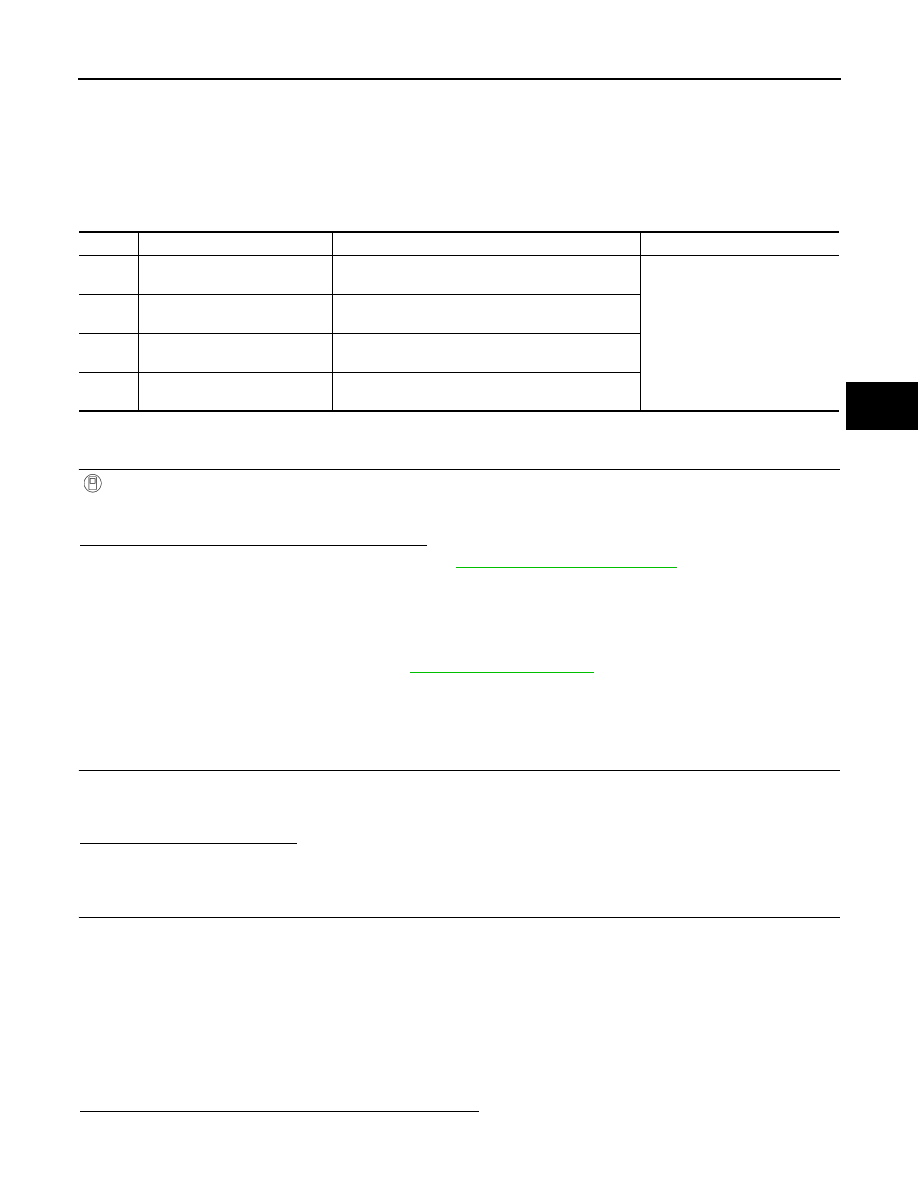
DTC
Display Item
Malfunction detected condition
Possible causes
C1101
RR RH SENSOR-1
When an open circuit is detected in rear wheel sensor
RH circuit.
• Harness or connector
• Wheel sensor
• ABS actuator and electric unit
(control unit)
C1102
RR LH SENSOR-1
When an open circuit is detected in rear wheel sensor
LH circuit.
C1103
FR RH SENSOR-1
When an open circuit is detected in front wheel sen-
sor RH circuit.
C1104
FR LH SENSOR-1
When an open circuit is detected in front wheel sen-
sor LH circuit.