Nissan Pathfinder (2012 year). Instruction - part 407


  Index      Instructions     Nissan Pathfinder (2012 year) - Service and Repair Instruction


Search            copyright infringement  


Content      ..     405      406      407      408     ..


Nissan Pathfinder (2012 year). Instruction - part 407


REFRIGERATION SYSTEM

HA-37

< REMOVAL AND INSTALLATION >

C

D

E

F

G

H

J

K

L

M

A

B

HA

N

O

P

recovery equipment. If an accidental system discharge occurs, ventilate the work area before resum-

ing service. Additional health and safety information may be obtained from the refrigerant and oil man-

ufacturers.

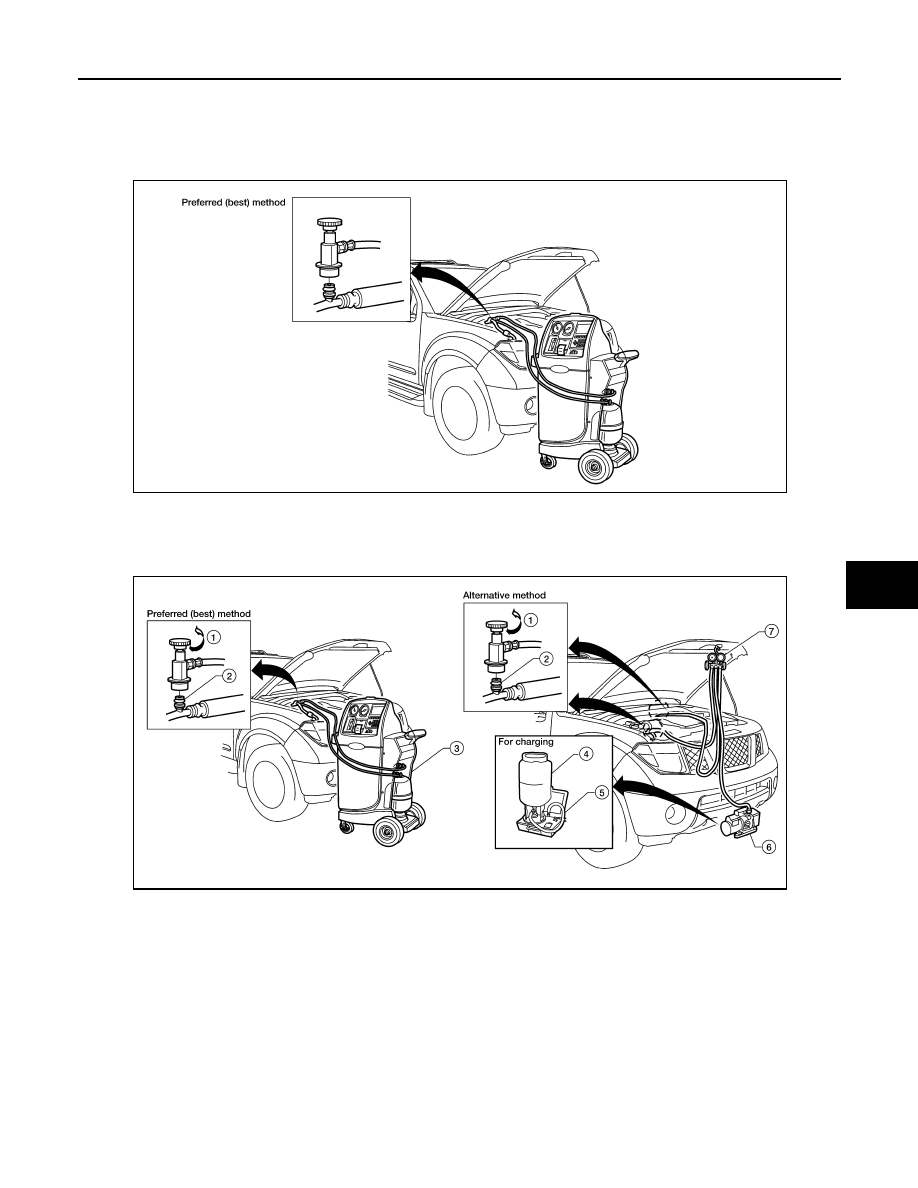
Discharging Refrigerant

Evacuating System and Charging Refrigerant

1.

Shut-off valve

2.

A/C service valve

3.

Recovery/recycling equipment

WJIA1160E

1.

Shut-off valve

2.

A/C service valve

3.

Recovery/recycling equipment

4.

Refrigerant container (HFC-134a)

5.

Refrigerant weight scale (J-39699)

6.

Vacuum pump (J-39649)

7.

Manifold gauge set with hoses and 
couplers (J-39183-C)

WJIA1161E

August 2012

2012 Pathfinder

HA-38

< REMOVAL AND INSTALLATION >

COMPRESSOR

COMPRESSOR

Removal and Installation for Compressor

INFOID:0000000007356317

A/C Compressor Mounting - VK56DE

CAUTION:

Tighten the compressor bolts to specification in the order shown.

AWIIA1291GB

August 2012

2012 Pathfinder

COMPRESSOR

HA-39

< REMOVAL AND INSTALLATION >

C

D

E

F

G

H

J

K

L

M

A

B

HA

N

O

P

A/C Compressor Mounting - VQ40DE

REMOVAL

1. Discharge the A/C refrigerant. Refer to 

HA-36, "HFC-134a (R-134a) Service Procedure"

.

2. Remove the front left wheel and tire assembly. Refer to 

WT-50, "Adjustment"

.

3. Remove the front left fender protector. Refer to 

EXT-25, "Removal and Installation of Front Fender Protec-

tor"

.

4. Reposition the crankcase ventilation hose out of the way.
5. Remove the power steering cooler hose bracket bolt (VK56DE only).
6. Remove the drive belt. Refer to 

EM-152, "Removal and Installation"

 (VK56DE), 

EM-26, "Removal and

Installation"

 (VQ40DE).

7. Disconnect the compressor harness connector.
8. Disconnect both the front high-pressure flexible A/C hose and front low-pressure flexible A/C hose from

the compressor. Refer to 

HA-34, "Component"

.

CAUTION:

Cap or wrap the joint of the pipe with suitable material such as vinyl tape to avoid the entry of air. 

9. Remove the A/C compressor bolts using power tools.

INSTALLATION

Installation is in the reverse order of removal.

CAUTION:

• Tighten the compressor bolts to specification in the order shown above (VK56DE).

• Do not reuse O-rings.

• Apply A/C oil to the O-ring of the front low-pressure flexible A/C hose and front high-pressure flexi-

ble A/C hose for installation.

• After recharging the A/C system with refrigerant, check for leaks. Refer to 

HA-29, "Checking of

Refrigerant Leaks"

.

LJIA0176E

1.

Compressor

2.

Front timing chain case

3.

Rear timing chain case

4.

Cylinder block

August 2012

2012 Pathfinder

HA-40

< REMOVAL AND INSTALLATION >

COMPRESSOR

Removal and Installation for Compressor Clutch

INFOID:0000000007356318

Magnet Clutch Assembly - VK56DE

Magnet Clutch Assembly - VQ40DE

NOTE:

Illustrations for removal and installation are shown with the compressor out of the vehicle for clarity.

REMOVAL

1. For VQ40DE, remove the engine cooling fan. Refer to 

CO-20, "Removal and Installation (Crankshaft

driven type)"

.

2. For VK56DE, remove the compressor. Refer to 

HA-38, "Removal and Installation for Compressor"

.

AWIIA1286GB

1.

Magnet clutch assembly

2.

Magnet coil

3.

Pulley

4.

Clutch disc

5.

Snap ring

6.

Thermal protector (built in)

7.

Compressor

AWIIA1284GB

1.

Magnet clutch assembly

2.

Magnet coil

3.

Pulley

4.

Clutch disc

5.

Snap ring

6.

Thermal protector (built in)

7.

Compressor

August 2012

2012 Pathfinder

COMPRESSOR

HA-41

< REMOVAL AND INSTALLATION >

C

D

E

F

G

H

J

K

L

M

A

B

HA

N

O

P

3. Remove the center bolt while holding the clutch disc stationary

using Tool as shown.

4. Remove the clutch disc and shims.

CAUTION:

Retain shims for installation.

5. Remove the snap ring using a suitable tool.

6. Remove the pulley using a suitable tool (A).

CAUTION:

To prevent deformation of the pulley groove, the puller

claws should be hooked under the pulley groove and not

into the pulley groove.

7. Remove the magnet coil.

• For the VK56DE engine, using a suitable tool remove the

three magnet coil screws and remove the magnet coil.

Tool number

: J-44614

WHA228

RHA072C

AWIIA1285ZZ

WHA212

August 2012

2012 Pathfinder

HA-42

< REMOVAL AND INSTALLATION >

COMPRESSOR

• For the VQ40DE engine, remove the magnet coil snap ring (A)

using a suitable tool and remove the magnet coil (1).

INSPECTION

Clutch Disc

If the contact surface shows signs of damage due to excessive heat, replace clutch disc and pulley.

Pulley

Check the appearance of the pulley assembly. If contact surface of pulley shows signs of excessive grooving,

replace clutch disc and pulley. The contact surfaces of the pulley assembly should be cleaned with a suitable

solvent before reinstallation.

Coil

Check magnet coil for loose connections or any cracked insulation. Replace as necessary.

INSTALLATION

1. Install the magnet coil.

• For the VK56DE engine, position the magnet coil and, using a

suitable tool, install the three magnet coil screws.

• For the VQ40DE engine, position the magnet coil (1) and

install the magnet coil snap ring (A) using a suitable tool.

CAUTION:

Be sure to align the magnet coil pin with the hole in the

compressor front head.

ALIIA0379ZZ

WHA212

ALIIA0379ZZ

August 2012

2012 Pathfinder

COMPRESSOR

HA-43

< REMOVAL AND INSTALLATION >

C

D

E

F

G

H

J

K

L

M

A

B

HA

N

O

P

2. Install the pulley assembly using Tool and a wrench, then install

the snap ring using a suitable tool.

3. Install the clutch disc on the compressor shaft, together with the

original shim(s) using a suitable tool. Press the clutch disc in by

hand.

4. Install the clutch pulley bolt while using Tool to prevent the clutch

disc from turning and tighten the bolt to specification.

CAUTION:

After tightening the clutch pulley bolt, check that the clutch

pulley rotates smoothly.

5. Check the pulley clearance all the way around the clutch disc as

shown.

6. If the specified clearance is not obtained, replace the adjusting

spacer to readjust.

Tool number

: — (J-38873-A)

WJIA1016E

WHA184

Tool number

: J-44614

WHA229

Clutch disc-to-pulley clearance

: 0.3 - 0.6 mm 
(0.012 - 0.024 in)

WHA194

August 2012

2012 Pathfinder

HA-44

< REMOVAL AND INSTALLATION >

COMPRESSOR

7. For VK56DE, install the compressor. Refer to 

HA-38, "Removal and Installation for Compressor"

.

8. For VQ40DE, install the engine cooling fan. Refer to 

CO-20, "Removal and Installation (Crankshaft driven

type)"

.

BREAK-IN OPERATION

When replacing compressor clutch assembly, always conduct the break-in operation. This is done by engag-

ing and disengaging the clutch about 30 times. Break-in operation raises the level of transmitted torque.

August 2012

2012 Pathfinder


Content      ..     405      406      407      408     ..