Nissan Pathfinder (2005 year). Instruction - part 159
 

  Index      Instructions     Nissan Pathfinder (2005 year) - Service and Repair Instruction


Search            copyright infringement  


Content      ..     157      158      159      160     ..


Nissan Pathfinder (2005 year). Instruction - part 159


TROUBLE DIAGNOSIS

EC-123

C

D

E

F

G

H

I

J

K

L

M

A

EC

2005 Pathfinder

78

GR

Sensor ground
(Heated oxygen sensor)

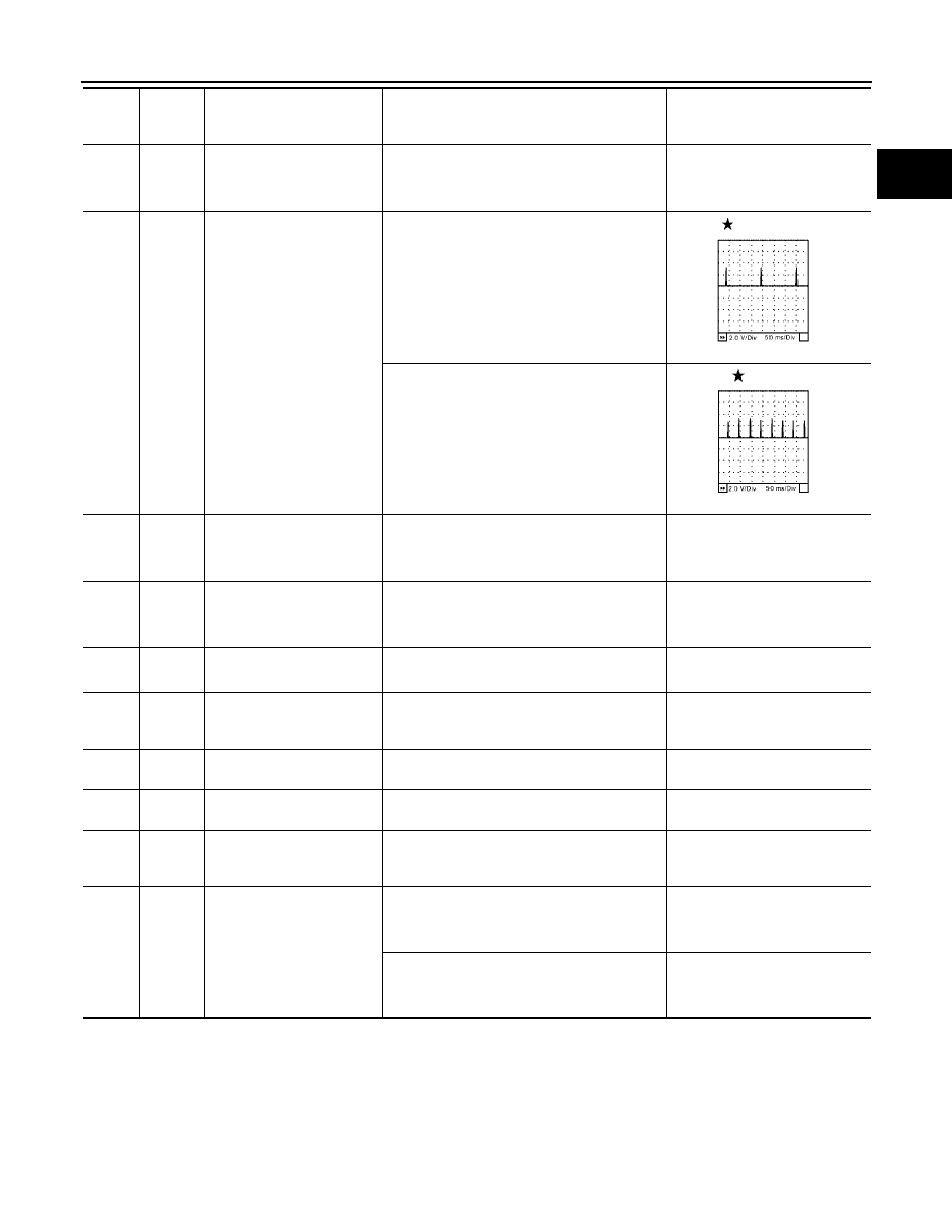
[Engine is running]

●

Warm-up condition

●

Idle speed

Approximately 0V

79
80
81

P
GR
G

Ignition signal No. 6
Ignition signal No. 4
Ignition signal No. 2

[Engine is running]

●

Warm-up condition

●

Idle speed

NOTE:
The pulse cycle changes depending on rpm
at idle

0 - 0.2V

[Engine is running]

●

Warm-up condition

●

Engine speed: 2,500 rpm

0.1 - 0.4V

82

B

Sensor ground
(APP sensor 1, ASCD steer-
ing switch

[Engine is running]

●

Warm-up condition

●

Idle speed

Approximately 0V

83

B

Sensor ground
(APP sensor 2)

[Engine is running]

●

Warm-up condition

●

Idle speed

Approximately 0V

85

W

Data link connector

[Ignition switch: ON]

●

CONSULT-II or GST: disconnected

Approximately 5V - Battery volt-
age (11 - 14V)

86

P

CAN communication line

[Ignition switch: ON]

Approximately 1.1 - 2.3V
Output voltage varies with the
communication status.

90

L

Sensor power supply
(APP sensor 1)

[Ignition switch: ON]

Approximately 5V

91

G

Sensor power supply
(APP sensor 2)

[Ignition switch: ON]

Approximately 5V

94

L

CAN communication line

[Ignition switch: ON]

Approximately 2.6 - 3.2V
Output voltage varies with the
communication status.

98

GR

Accelerator pedal position
sensor 2

[Ignition switch: ON]

●

Engine: Stopped

●

Accelerator pedal: Fully released

0.28 - 0.48V

[Ignition switch: ON]

●

Engine: Stopped

●

Accelerator pedal: Fully depressed

More than 2.0

TER-

MINAL

NO.

WIRE

COLOR

ITEM

CONDITION

DATA (DC Voltage)

SEC986C

SEC987C

EC-124

TROUBLE DIAGNOSIS

2005 Pathfinder

99

SB

ASCD steering switch

[Ignition switch: ON]

●

ASCD steering switch: OFF

Approximately 4.0V

[Ignition switch: ON]

●

MAIN switch: Pressed

Approximately 0V

[Ignition switch: ON]

●

CANCEL switch: Pressed

Approximately 1V

[Ignition switch: ON]

●

RESUME/ACCELERATE switch: Pressed

Approximately 3V

[Ignition switch: ON]

●

SET/COAST switch: Pressed

Approximately 2V

101

LG

Stop lamp switch

[Ignition switch: OFF]

●

Brake pedal: Fully released

Approximately 0V

[Ignition switch: OFF]

●

Brake pedal: Slightly depressed

BATTERY VOLTAGE
(11 - 14V)

102

G

PNP switch

[Ignition switch: ON]

●

Shift lever: P or N

Approximately 0V

[Ignition switch: ON]

●

Except above position

BATTERY VOLTAGE
(11 - 14V)

104

O

Throttle control motor relay

[Ignition switch: OFF]

BATTERY VOLTAGE
(11 - 14V)

[Ignition switch: ON]

0 - 1.0V

106

R

Accelerator pedal position
sensor 1

[Ignition switch: ON]

●

Engine: Stopped

●

Accelerator pedal: Fully released

0.65 - 0.87V

[Ignition switch: ON]

●

Engine: Stopped

●

Accelerator pedal: Fully depressed

More than 4.3V

107

Y

Fuel tank temperature sen-
sor

[Engine is running]

Approximately 0 - 4.8V
Output voltage varies with fuel
tank temperature.

108

LG

ASCD brake switch

[Ignition switch: ON]

●

Brake pedal: Slightly depressed

Approximately 0V

[Ignition switch: ON]

●

Brake pedal: Fully released

BATTERY VOLTAGE
(11 - 14V)

109

W/R

Ignition switch

[Ignition switch: OFF]

0V

[Ignition switch: ON]

BATTERY VOLTAGE
(11 - 14V)

111

BR

ECM relay
(Self shut-off)

[Engine is running]
[Ignition switch: OFF]

●

For a few seconds after turning ignition
switch OFF

0 - 1.5V

[Ignition switch: OFF]

●

More than a few seconds after turning igni-
tion switch OFF

BATTERY VOLTAGE
(11 - 14V)

TER-

MINAL

NO.

WIRE

COLOR

ITEM

CONDITION

DATA (DC Voltage)

TROUBLE DIAGNOSIS

EC-125

C

D

E

F

G

H

I

J

K

L

M

A

EC

2005 Pathfinder

: Average voltage for pulse signal (Actual pulse signal can be confirmed by oscilloscope.)

*: Before measuring the terminal voltage, confirm that the battery is fully charged. Refer to

SC-5, "SPECIFIC GRAVITY CHECK"

.

CONSULT-II Function (ENGINE)

UBS00K4C

FUNCTION

*: The following emission-related diagnostic information is cleared when the ECM memory is erased.

●

Diagnostic trouble codes

●

1st trip diagnostic trouble codes

●

Freeze frame data

●

1st trip freeze frame data

●

System readiness test (SRT) codes

●

Test values

113

Y

Fuel pump relay

[Ignition switch: ON]

●

For 1 second after turning ignition switch ON

[Engine is running]

0 - 1.5V

[Ignition switch: ON]

●

More than 1 second after turning ignition
switch ON

BATTERY VOLTAGE
(11 - 14V)

115
116

B
GR

ECM ground

[Engine is running]

●

Idle speed

Body ground

117

G

EVAP canister vent control
valve

[Ignition switch: ON]

BATTERY VOLTAGE
(11 - 14V)

119

120

R
P

Power supply for ECM

[Ignition switch: ON]

BATTERY VOLTAGE
(11 - 14V)

121

R/B

Power supply for ECM
(Back-up)

[Ignition switch: OFF]

BATTERY VOLTAGE
(11 - 14V)

TER-

MINAL

NO.

WIRE

COLOR

ITEM

CONDITION

DATA (DC Voltage)

Diagnostic test mode

Function

Work support

This mode enables a technician to adjust some devices faster and more accurately by following the
indications on the CONSULT-II unit.

Self-diagnostic results

Self-diagnostic results such as 1st trip DTC, DTCs and 1st trip freeze frame data or freeze frame data
can be read and erased quickly.*

Data monitor

Input/Output data in the ECM can be read.

Data monitor (SPEC)

Input/Output of the specification for Basic fuel schedule, AFM, A/F feedback control value and the
other data monitor items can be read.

CAN diagnostic support
monitor

The results of transmit/receive diagnosis of CAN communication can be read.

Active test

Diagnostic Test Mode in which CONSULT-II drives some actuators apart from the ECMs and also
shifts some parameters in a specified range.

Function test

This mode is used to inform customers when their vehicle condition requires periodic maintenance.

DTC & SRT confirmation

The status of system monitoring tests and the self-diagnosis status/result can be confirmed.

ECM part number

ECM part number can be read.

EC-126

TROUBLE DIAGNOSIS

2005 Pathfinder

ENGINE CONTROL COMPONENT PARTS/CONTROL SYSTEMS APPLICATION

Item

DIAGNOSTIC TEST MODE

WORK

SUP-

PORT

SELF-DIAGNOSTIC

RESULTS

DATA

MONI-

TOR

DATA

MONI-

TOR

(SPEC)

ACTIVE

TEST

DTC & SRT

CONFIRMATION

DTC*1

FREEZE

FRAME
DATA*2

SRT

STATUS

DTC

WORK

SUP-

PORT

ENGINE

C

ONTROL

COMPONENT

P

ARTS

IN

P

U

T

Crankshaft position sensor (POS)

×

×

×

×

Camshaft position sensor (PHASE)

×

×

×

×

Mass air flow sensor

×

×

×

Engine coolant temperature sensor

×

×

×

×

×

Air fuel ratio (A/F) sensor 1

×

×

×

×

×

Heated oxygen sensor 2

×

×

×

×

×

Wheel sensor

×

×

×

×

Accelerator pedal position sensor

×

×

×

Throttle position sensor

×

×

×

Fuel tank temperature sensor

×

×

×

×

EVAP control system pressure
sensor

×

×

×

Intake air temperature sensor

×

×

×

×

Knock sensor

×

Refrigerant pressure sensor

×

×

Closed throttle position switch
(accelerator pedal position sensor
signal)

×

×

Air conditioner switch

×

×

Park/neutral position (PNP) switch

×

×

×

Stop lamp switch

×

×

×

Power steering pressure sensor

×

×

×

Battery voltage

×

×

Load signal

×

×

Fuel level sensor

×

×

×

Battery current sensor

×

×

×

ASCD steering switch

×

×

×

ASCD brake switch

×

×

×

TROUBLE DIAGNOSIS

EC-127

C

D

E

F

G

H

I

J

K

L

M

A

EC

2005 Pathfinder

X: Applicable
*1: This item includes 1st trip DTCs.
*2: This mode includes 1st trip freeze frame data or freeze frame data. The items appear on CONSULT-II screen in freeze frame data
mode only if a 1st trip DTC or DTC is detected. For details, refer to

EC-129

.

INSPECTION PROCEDURE

CAUTION:

If CONSULT-II is used with no connection of CONSULT-II CONVERTER, malfunctions might be
detected in self-diagnosis depending on control unit which carry out CAN communication.

1.

Turn ignition switch OFF.

2.

Connect CONSULT-II and CONSULT-II CONVERTER to data
link connector, which is located under LH dash panel near the
hood opener handle.

3.

Turn ignition switch ON.

ENGI

NE

CONTROL

C

OMPONENT

P

ARTS

OUTPUT

Fuel injector

×

×

×

Power transistor (Ignition timing)

×

×

×

Throttle control motor relay

×

×

×

Throttle control motor

×

EVAP canister purge volume con-
trol solenoid valve

×

×

×

×

×

Air conditioner relay

×

×

Fuel pump relay

×

×

×

×

Cooling fan relay

×

×

×

×

Air fuel ratio (A/F) sensor 1 heater

×

×

×

×

Heated oxygen sensor 2 heater

×

×

×

×

EVAP canister vent control valve

×

×

×

×

×

Intake valve timing control solenoid
valve

×

×

×

×

VIAS control solenoid valve

×

×

×

×

Alternator

×

×

×

Calculated load value

×

×

×

Item

DIAGNOSTIC TEST MODE

WORK

SUP-

PORT

SELF-DIAGNOSTIC

RESULTS

DATA

MONI-

TOR

DATA

MONI-

TOR

(SPEC)

ACTIVE

TEST

DTC & SRT

CONFIRMATION

DTC*1

FREEZE

FRAME
DATA*2

SRT

STATUS

DTC

WORK

SUP-

PORT

BBIA0538E

EC-128

TROUBLE DIAGNOSIS

2005 Pathfinder

4.

Touch “START (NISSAN BASED VHCL)”.

5.

Touch “ENGINE”.
If “ENGINE” is not indicated, go to

GI-38, "CONSULT-II Data

Link Connector (DLC) Circuit"

.

6.

Perform each diagnostic test mode according to each service
procedure.

For further information, see the CONSULT-II Operation Instruction.

WORK SUPPORT MODE
Work Item

BCIA0029E

BCIA0030E

BCIA0031E

WORK ITEM

CONDITION

USAGE

FUEL PRESSURE RELEASE

●

FUEL PUMP WILL STOP BY TOUCHING “START” DUR-
ING IDLING.
CRANK A FEW TIMES AFTER ENGINE STALLS.

When releasing fuel pressure
from fuel line

IDLE AIR VOL LEARN

●

THE IDLE AIR VOLUME THAT KEEPS THE ENGINE
WITHIN THE SPECIFIED RANGE IS MEMORIZED IN
ECM.

When learning the idle air volume

SELF-LEARNING CONT

●

THE COEFFICIENT OF SELF-LEARNING CONTROL
MIXTURE RATIO RETURNS TO THE ORIGINAL COEF-
FICIENT.

When clearing the coefficient of
self-learning control value

TROUBLE DIAGNOSIS

EC-129

C

D

E

F

G

H

I

J

K

L

M

A

EC

2005 Pathfinder

*: This function is not necessary in the usual service procedure.

SELF-DIAG RESULTS MODE
Self Diagnostic Item

Regarding items of DTC and 1st trip DTC, refer to

EC-49, "EMISSION-RELATED DIAGNOSTIC INFORMA-

TION ITEMS"

.

Freeze Frame Data and 1st Trip Freeze Frame Data

EVAP SYSTEM CLOSE

CLOSE THE EVAP CANISTER VENT CONTROL VALVE IN
ORDER TO MAKE EVAP SYSTEM CLOSE UNDER THE
FOLLOWING CONDITIONS.

●

IGN SW ON

●

ENGINE NOT RUNNING

●

AMBIENT TEMPERATURE IS ABOVE 0

°

C (32

°

F).

●

NO VACUUM AND NO HIGH PRESSURE IN EVAP SYS-
TEM

●

FUEL TANK TEMP. IS MORE THAN 0

°

C (32

°

F).

●

WITHIN 10 MINUTES AFTER STARTING “EVAP SYS-
TEM CLOSE”

●

WHEN TRYING TO EXECUTE “EVAP SYSTEM CLOSE”
UNDER THE CONDITION EXCEPT ABOVE, CONSULT-
II WILL DISCONTINUE IT AND DISPLAY APPROPRI-
ATE INSTRUCTION.

NOTE:
WHEN STARTING ENGINE, CONSULT-II MAY DISPLAY
“BATTERY VOLTAGE IS LOW. CHARGE BATTERY”,
EVEN IN USING CHARGED BATTERY.

When detecting EVAP vapor leak
point of EVAP system

VIN REGISTRATION

●

IN THE MODE, VIN IS REGISTERED IN ECM.

When registering VIN in ECM

TARGET IDLE RPM ADJ*

●

IDLE CONDITION

When setting target idle speed

TARGET IGN TIM ADJ*

●

IDLE CONDITION

When adjusting target ignition tim-
ing

WORK ITEM

CONDITION

USAGE

Freeze frame data

item*

Description

DIAG TROUBLE
CODE
[PXXXX]

●

The engine control component part/control system has a trouble code, it is displayed as “PXXXX”. (Refer
to

EC-9, "INDEX FOR DTC"

.)

FUEL SYS-B1

●

“Fuel injection system status” at the moment a malfunction is detected is displayed.

●

One mode in the following is displayed.
“Mode2”: Open loop due to detected system malfunction
“Mode3”: Open loop due to driving conditions (power enrichment, deceleration enleanment)
“Mode4”: Closed loop - using oxygen sensor(s) as feedback for fuel control
“Mode5”: Open loop - has not yet satisfied condition to go to closed loop

FUEL SYS-B2

CAL/LD VALUE [%]

●

The calculated load value at the moment a malfunction is detected is displayed.

COOLANT TEMP [

°

C]

or [

°

F]

●

The engine coolant temperature at the moment a malfunction is detected is displayed.

L-FUEL TRM-B1 [%]

●

“Long-term fuel trim” at the moment a malfunction is detected is displayed.

●

The long-term fuel trim indicates much more gradual feedback compensation to the base fuel schedule
than short-term fuel trim.

L-FUEL TRM-B2 [%]

S-FUEL TRM-B1 [%]

●

“Short-term fuel trim” at the moment a malfunction is detected is displayed.

●

The short-term fuel trim indicates dynamic or instantaneous feedback compensation to the base fuel
schedule.

S-FUEL TRM-B2 [%]

ENGINE SPEED
[rpm]

●

The engine speed at the moment a malfunction is detected is displayed.

VEHICL SPEED [km/
h] or [mph]

●

The vehicle speed at the moment a malfunction is detected is displayed.

EC-130

TROUBLE DIAGNOSIS

2005 Pathfinder

*: The items are the same as those of 1st trip freeze frame data.

B/FUEL SCHDL
[msec]

●

The base fuel schedule at the moment a malfunction is detected is displayed.

INT/A TEMP SE [

°

C]

or [

°

F]

●

The intake air temperature at the moment a malfunction is detected is displayed.

Freeze frame data

item*

Description


Content      ..     157      158      159      160     ..