Nissan Pathfinder. Instruction - part 849
CHASSIS AND BODY MAINTENANCE
MA-35
< PERIODIC MAINTENANCE >
C
D
E
F
G
H
I
J
K
L
M
B
MA
N
O
A
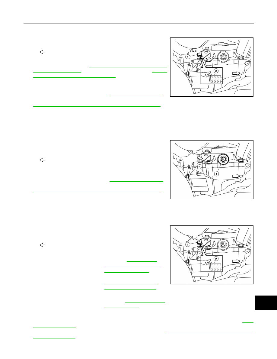
CAUTION:
Do not start engine while checking oil level.
1. Remove filler plug (1).
2. Oil level (A) should be level with bottom of filler plug hole. Add
oil if necessary. Refer to
(United States and Canada) or
"FOR MEXICO : Fluids and Lubricants"
3. Clean threads of filler plug (1) and transfer case.
4. Apply sealant to the threads of the filler plug (1) and install it.
Tighten to specified torque. Refer to
Use Genuine Silicone RTV Sealant or equivalent. Refer to
GI-22, "Recommended Chemical Products and Sealants"
.
TRANSFER OIL : Draining
INFOID:0000000009174192
CAUTION:
Do not start engine while checking oil level.
1. Run the vehicle to warm up the transfer unit sufficiently.
2. Stop the engine and remove drain plug (1) and drain the transfer
oil.
3. Clean threads of drain plug (1) and transfer case.
4. Apply sealant to the threads of the drain plug (1) and install it.
Tighten to specified torque. Refer to
Use Genuine Silicone RTV Sealant or equivalent. Refer to
GI-22, "Recommended Chemical Products and Sealants"
.
TRANSFER OIL : Refilling
INFOID:0000000009174193
CAUTION:
Do not start engine while checking oil level.
1. Remove filler plug (1).
2. Fill with new oil to the specified level near the filler plug hole.
3. Clean threads of filler plug (1) and transfer case.
4. Apply sealant to the threads of the filler plug (1), and install it. Tighten to specified torque. Refer to
Use Genuine Silicone RTV Sealant or equivalent. Refer to
GI-22, "Recommended Chemical Prod-
.
: Front
ALDIA0383ZZ
: Front
ALDIA0382ZZ
: Front
Oil grade and viscosity
: Refer to
USA AND CANADA : Flu-
ids and Lubricants"
(Unit-
ed States and Canada) or
MA-16, "FOR MEXICO :
Fluids and Lubricants"
(Mexico).
Oil capacity
: Refer to
.
ALDIA0383ZZ