Nissan Pathfinder. Instruction - part 848
CHASSIS AND BODY MAINTENANCE
MA-31
< PERIODIC MAINTENANCE >
C
D
E
F
G
H
I
J
K
L
M
B
MA
N
O
A
CHASSIS AND BODY MAINTENANCE
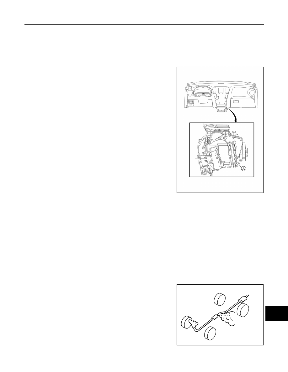
IN-CABIN MICROFILTER
IN-CABIN MICROFILTER : Removal and Installation
INFOID:0000000009174186
REMOVAL
1. Release the in-cabin microfilter cover tab (A) and remove the
cover from under the (RH) side of the instrument panel.
CAUTION:
Use care when lifting up on the tab to avoid damaging it.
2. Remove the in-cabin microfilter.
CAUTION:
If the filter is deformed/damaged when removing, replace it with a new one. A deformed or dam-
aged filter may affect the dust collecting performance.
INSTALLATION
Installation is in the reverse order of removal.
CAUTION:
When installing, handle the filter with extreme care to avoid deforming or damaging the filter.
NOTE:
The in-cabin microfilter is marked with an air flow arrow. The end of the microfilter with the arrow should face
the passenger side of the vehicle. The arrow should point towards the rear of the vehicle.
EXHAUST SYSTEM
EXHAUST SYSTEM : Inspection
INFOID:0000000009174187
Check exhaust pipes, muffler and mounting for improper attachment,
leaks, cracks, damage or deterioration. Repair or replace as neces-
sary.
CVT FLUID
AWIIA1577ZZ
SMA211A