Nissan Pathfinder. Instruction - part 751


  Index      Nissan     Nissan Pathfinder (2014 year) - Service and Repair Instruction


Search            copyright infringement  


Content   ..  749  750  751  752   ..


Nissan Pathfinder. Instruction - part 751


BODY SIDE TRIM

INT-23

< REMOVAL AND INSTALLATION >

C

D

E

F

G

H

I

K

L

M

A

B

INT

N

O

P

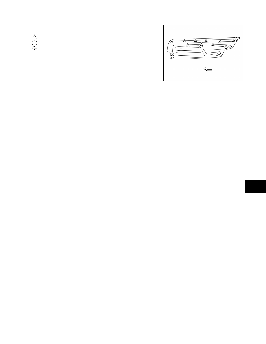
1. Release the rear kicking plate clips and pawls using a suitable

tool.

: Clip
: Pawl

: Front

2. Remove the rear kicking plate.

INSTALLATION

Installation is in the reverse order of removal.

CAUTION:

• Visually check the clips and pawls for deformation and damage during installation. Replace with new

ones if necessary.

• When installing rear kicking plate, check that the clips and pawls are securely placed in body panel

holes.

ALJIA0813ZZ

INT-24

< REMOVAL AND INSTALLATION >

FLOOR TRIM

FLOOR TRIM

Exploded View

INFOID:0000000009176415

Removal and Installation

INFOID:0000000009176416

FRONT FLOOR TRIM

Removal

CAUTION:

Before servicing, turn the ignition switch off, disconnect both battery cables and wait at least three

minutes.
1. Disconnect the negative battery terminal, then wait at least three minutes. Refer to 

PG-90, "Removal and

Installation"

2. Remove the front kicking plates (LH/RH). Refer to 

INT-22, "KICKING PLATE : Removal and Installation -

Front Kicking Plate"

.

3. Remove the rear kicking plates (LH/RH). Refer to 

INT-22, "KICKING PLATE : Removal and Installation -

Rear Kicking Plate"

.

4. Remove the front seat assemblies (LH/RH). Refer to 

SE-86, "Removal and Installation"

.

1.

Front floor trim cover

2.

Front floor trim

1.

Rear floor trim

A.

Front floor trim bracket

Front

AWJIA1174ZZ

FLOOR TRIM

INT-25

< REMOVAL AND INSTALLATION >

C

D

E

F

G

H

I

K

L

M

A

B

INT

N

O

P

5. Remove the rear blower motor 1 unit assembly. Refer to 

VTL-20, "REAR BLOWER MOTOR 1 UNIT

ASSEMBLY : Removal and Installation"

.

6. Remove the front floor connecting duct (LH/RH). Refer to 

VTL-11, "FRONT FLOOR DUCT : Removal and

Installation - Front Floor Connecting Duct"

.

7. Remove the instrument panel lower bracket bolt and screw, then reposition bracket as necessary to

remove floor trim.

8. Remove the center console brace bolts and remove. Refer to 

IP-18, "Exploded View"

9. Remove the second row seats. Refer to 

SE-94, "Removal and Installation"

.

10. Remove the front floor trim.

Installation

Installation is in the reverse order of removal.

REAR FLOOR TRIM

Removal

1. Disconnect the negative battery terminal, then wait at least three minutes. Refer to 

PG-90, "Removal and

Installation"

2. Remove the back door kicking plate. Refer to 

INT-36, "BACK DOOR KICKING PLATE : Removal and

Installation"

3. Remove the luggage side lower finishers (LH/RH). Refer to 

INT-31, "LUGGAGE SIDE LOWER FINISHER

: Removal and Installation"

.

4. Remove the rear floor trim.

Installation

Installation is in the reverse order of removal.

INT-26

< REMOVAL AND INSTALLATION >

HEADLINING

HEADLINING

Exploded View

INFOID:0000000009176417

With moonroofs

AWJIA1156ZZ

1.

Headlining

2.

Rear assist grip (RH)

3.

Personal lamp (RH)

4.

Front assist grip (RH)

5.

Sun visor (RH)

6.

Front room/map lamp assembly

7.

Headlining access cover

8.

Sun visor (LH)

9.

Front assist grip (LH)

10. Personal lamp (LH)

11. Rear assist grip (LH)

12. Cargo lamp

A.

Magnetic clip

Front


Content   ..  749  750  751  752   ..