Nissan Pathfinder. Instruction - part 411
DLN-86
< UNIT DISASSEMBLY AND ASSEMBLY >
[TRANSFER: TY21C]
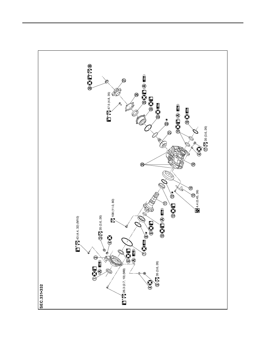
DRIVE PINION
DRIVE PINION
Exploded View
INFOID:0000000009177783
1.
Oil seal
2.
Transfer cover
3.
Filler plug
4.
Gasket
5.
Drain plug
6.
Oil seal
JSDIA4191GB