Nissan Pathfinder. Instruction - part 132


  Index      Nissan     Nissan Pathfinder (2014 year) - Service and Repair Instruction


Search            copyright infringement  


Content   ..  130  131  132  133   ..


Nissan Pathfinder. Instruction - part 132


AV

STEERING SWITCH

AV-355

< DTC/CIRCUIT DIAGNOSIS >

[MID AUDIO WITH BOSE]

C

D

E

F

G

H

I

J

K

L

M

B

A

O

P

STEERING SWITCH

Diagnosis Procedure

INFOID:0000000009174615

Regarding Wiring Diagram information, refer to 

AV-242, "Wiring Diagram"

.

1.

CHECK STEERING WHEEL AUDIO CONTROL SWITCH RESISTANCE

1. Turn ignition switch OFF.

2. Disconnect combination switch connector M149.

3. Check the resistance between the terminals of combination switch connector M149.

Is the inspection result normal?

YES

>> GO TO 2.

NO

>> Replace steering wheel audio control switch. Refer to 

AV-368, "Removal and Installation"

.

2.

CHECK HARNESS BETWEEN COMBINATION SWITCH AND COMBINATION METER

1. Disconnect combination meter connector M24 and combination switch connector M30.

2. Check continuity between combination meter connector M24 and combination switch connector M30.

3. Check continuity between combination meter connector M24 and ground.

Is the inspection result normal?

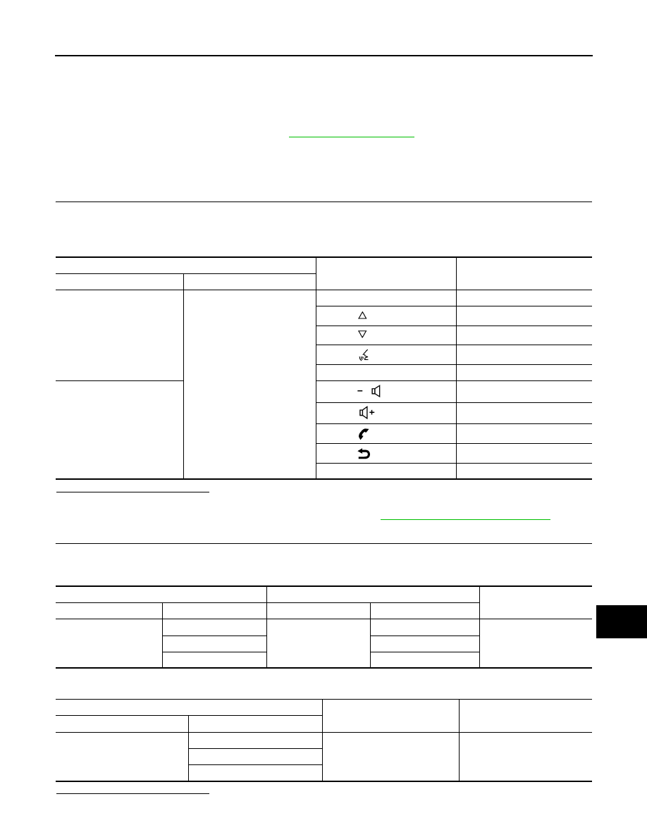
Combination switch connector M149

Condition

Resistance 

(Approx.)

Terminal

Terminal

14

17

Depress SOURCE switch.

1

Depress  

switch.

121

Depress  

switch.

321

Depress  

switch.

723

Depress ENTER switch.

2023

15

Depress  

switch.

1

Depress  

switch.

121

Depress  

switch. 

321

Depress  

switch. 

723

Depress DISP switch.

2023

Combination meter

Combination switch 

Continuity

Connector

Terminal

Connector

Terminal

M24

3

M30

24

Yes

24

33

4

31

Combination meter

Ground

Continuity

Connector

Terminal

M24

3

No

24

4

AV-356

< DTC/CIRCUIT DIAGNOSIS >

[MID AUDIO WITH BOSE]

STEERING SWITCH

YES

>> GO TO 3.

NO

>> Repair or replace harness or connectors.

3.

CHECK COMBINATION SWITCH

Check continuity between combination switch connectors M30 and M149.

Is the inspection result normal?

YES

>> GO TO 4.

NO

>> Replace spiral cable. Refer to 

SR-15, "Removal and Installation"

.

4.

CHECK HARNESS BETWEEN COMBINATION METER AND AV CONTROL UNIT 

1. Disconnect AV control unit connector M44.

2. Check continuity between combination meter connector M24 and AV control unit connector M44.

3. Check continuity between combination meter connector M24 and ground.

Is the inspection result normal?

YES

>> GO TO 5.

NO

>> Repair or replace harness or connectors.

5.

CHECK AV CONTROL UNIT VOLTAGE

1. Connect combination meter connector M24 and AV control unit connector M44.

2. Turn ignition switch ON.

3. Check the voltage between the terminals of AV control unit connector M44.

Is the inspection result normal?

YES

>> Replace combination meter. Refer to 

MWI-82, "Removal and Installation"

.

NO

>> Replace AV control unit. Refer to 

AV-365, "Removal and Installation"

.

Combination switch 

Continuity

Connector

Terminal

Connector

Terminal

M30

24

M149

14

Yes

31

15

33

17

Combination meter

AV control unit 

Continuity

Connector

Terminal

Connector

Terminal

M24

14

M44

38

Yes

15

48

16

47

Combination meter

Ground

Continuity

Connector

Terminal

M24

14

No

15

16

AV control unit M44

Voltage

(Approx.)

(+)

(

−)

Terminal

Terminal

38

47

5.0 V

48

AV

USB CONNECTOR

AV-357

< DTC/CIRCUIT DIAGNOSIS >

[MID AUDIO WITH BOSE]

C

D

E

F

G

H

I

J

K

L

M

B

A

O

P

USB CONNECTOR

Diagnosis Procedure

INFOID:0000000009174616

Regarding Wiring Diagram information, refer to 

AV-242, "Wiring Diagram"

.

1.

CHECK USB INTERFACE HARNESS CONTINUITY

1. Turn ignition switch OFF.

2. Disconnect AV control unit connector M145 and USB interface connector M209.

3. Check continuity between AV control unit connector M145 and USB interface connector M209.

4. Check continuity between AV control unit connector M55 and ground.

Is the inspection result normal?

YES

>> Replace the USB interface. Refer to 

AV-380, "Removal and Installation"

.

NO

>> Repair or replace harness or connectors.

AV control unit

USB interface 

Continuity

Connector

Terminal

Connector

Terminal

M145

121

M209

2

Yes

122

1

123

4

124

3

125

5

AV control unit

Continuity

Connector

Terminal

M145

121

Ground

No

123

AV-358

< SYMPTOM DIAGNOSIS >

[MID AUDIO WITH BOSE]

MULTI AV SYSTEM

SYMPTOM DIAGNOSIS

MULTI AV SYSTEM

Symptom Table

INFOID:0000000009174617

RELATED TO AUDIO

Symptoms

Check items

Probable malfunction location

The disk cannot be removed.

AV control unit

Malfunction in AV control unit.
Refer to 

AV-214, "On Board Diagnosis 

Function"

.


Content   ..  130  131  132  133   ..