Nissan Pathfinder. Instruction - part 131
AV
DISK EJECT SIGNAL CIRCUIT
AV-351
< DTC/CIRCUIT DIAGNOSIS >
[MID AUDIO WITH BOSE]
C
D
E
F
G
H
I
J
K
L
M
B
A
O
P
DISK EJECT SIGNAL CIRCUIT
Diagnosis Procedure
INFOID:0000000009174612
Regarding Wiring Diagram information, refer to
.
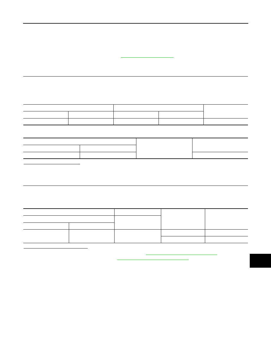
1.
CHECK DISK EJECT SIGNAL CIRCUIT CONTINUITY
1. Turn ignition switch OFF.
2. Disconnect AV control unit connector M42 and A/C and AV switch assembly connector.
3. Check continuity between AV control unit connector M42 terminal 28 and A/C and AV switch assembly
connector M98 terminal 14.
4. Check continuity between AV control unit connector M42 terminal 28 and ground.
Is inspection result normal?
YES
>> GO TO 2.
NO
>> Repair or replace harness or connectors.
2.
CHECK AV CONTROL UNIT VOLTAGE
1. Connect AV control unit connector M42 and A/C and AV switch assembly connector.
2. Turn ignition switch ON.
3. Check voltage between AV control unit connector M42 terminal 28 and ground.
Is the inspection result normal?
YES
>> Replace A/C and AV switch assembly. Refer to
AV-367, "Removal and Installation"
.
NO
>> Replace AV control unit. Refer to
AV-365, "Removal and Installation"
.
AV control unit
A/C and AV switch assembly
Continuity
Connector
Terminal
Connector
Terminal
M42
28
M98
14
Yes
AV control unit
Ground
Continuity
Connector
Terminal
M42
28
No
AV control unit
Ground
Condition
Voltage
(Approx.)
(+)
(
−)
Connector
Terminal
M42
28
—
Pressing eject switch
0 V
Except above
5.0 V