Isuzu N-Series. Service manual - part 875


  Index      Isuzu     Isuzu N-Series - service and repair manual


Search            


Content   ..  873  874  875  876   ..


Isuzu N-Series. Service manual - part 875


7B1-24 MANUAL TRANSMISSION (MZZ)

34. Install the retainer to the transmission case.

Tighten the bolts to the specified torque.

Tighten:
Bolts to 26 N

⋅m (2.7 kg⋅m / 20 lb⋅ft)

Notice:
Be sure to thoroughly remove sealing material from the
screw threads of the transmission housing, and to use a
set of new screws.

35. Install the speedometer gear.
36. Install the block and spring to the clutch hub.
37. Adjust the phase so that the three balls fit into the

three ball grooves inside the sleeve.

38. Insert the sleeve (1) into the clutch hub (5) until re-

sistance is felt.

39. Insert the ball (2), the block (3), and the spring (4)

into the clutch hub. Be sure that the ball enters the
ball groove.

• The arrow indicates the front of the transmission.

40. Apply engine oil (5W-30) to the neutral bearing and

the inside of the block ring.

41. Assemble the 6th gear the needle bearing, and the

6th gear block ring.

42. Align the above assembly with the clutch hub block

ring.

43. Assemble the 6th gear clutch hub assembly and

the sleeve.

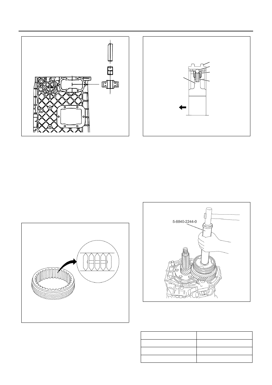
44. Use the installer (5-8840-2244-0) and a hammer to

install the assembled parts.

45. Use a pair of snap ring pliers to install the 6th gear

clutch hub snap ring.

• From the mountable snap rings, select the thickest

one of the three types.

N7A1090E

N7A1210E

Shim thickness mm (in)

Discernment color

1.6 (0.063)

Pink

1.7 (0.067)

Light blue

1.8 (0.071)

Orange

1

2

3

5

4

N7A0533E

N7A1176E

MANUAL TRANSMISSION (MZZ) 7B1-25

Notice:
If a snap ring is deformed or damaged, replace it with a
new one and verify that it is attached properly.

46. Apply engine oil (5W-30) to the shift rod holes in

the transmission case.

47. Install the 6th gear shift arm (3) and the 6th gear

shift rod (4).

48. Align the spring pin holes.
49. Insert the spring pins (2).
50. Install the relay lever 6th gear (1). Tighten the bolts

to the specified torque.

Tighten:
Bolts to 44 N

⋅m (4.5 kg⋅m / 34 lb⋅ft)

51. Apply multi-purpose type grease to the inside of

the main end needle bearing.

52. Apply engine oil (5W-30) to the inside contact sur-

faces of the rear cover bearing.

53. Use the installer (5-8840-2753-0) and the handle

(5-8840-0007-0) to press the needle bearing into
the rear cover from the outside. The inscribed mark
on the bearing must be facing out.

Caution:
The lipped portion of the oil seal is easily broken. Exer-
cise care during the installation procedure.

54. Inspect the rear cover oil seal for wear and dam-

age. If wear or damage is present, the oil seal must
be replaced.

55. Apply multi-purpose type grease to the lip portion

of the oil seal.

56. Apply engine oil (5W-30) to the outer circumfer-

ence of the oil seal.

57. Use the installer (5-8840-2751-0) to press the oil

seal into the rear cover.

58. Apply Three Bond 1215 to the contact surfaces of

the transmission case and the rear cover.

59. Install the rear cover to the transmission case.

Tighten the bolts to the specified torque.

• Remove moisture and oil from the fitting surface

prior to application. Set the bead diameter to great-
er than 2 mm (0.078 in) and make it even all
around.

Tighten:
Bolts to 46 N

⋅m (4.7 kg⋅m / 34 lb⋅ft)

1.9 (0.075)

Purple

Shim thickness mm (in)

Discernment color

N7A1140E

5-8840-0007-0

5-8840-2753-0

N7A0568E

5-8840-2751-0

N7A0567E

7B1-26 MANUAL TRANSMISSION (MZZ)

Notice:
The two bolts, indicated by the arrows, have lock-tight
material applied to them. Be sure to thoroughly remove
sealing material from the threads and to use new bolts
with lock-tight material.

60. Align the contact surfaces of the transmission case

reverse gear side cover.

61. Apply Three Bond 1215 to the contact surfaces.
62. Install the reverse gear side cover. Tighten the

bolts to the specified torque.

Tighten:
Bolts to 20 N

⋅m (2.0 kg⋅m / 15 lb⋅ft)

63. Align the contact surfaces of the transmission case

PTO cover.

64. Apply Three Bond 1215 to the contact surfaces.
65. Install the PTO cover. Tighten the bolts to the spec-

ified torque.

Tighten:
Bolts to 37 N

⋅m (3.8 kg⋅m / 27 lb⋅ft)

Notice:
The bolts have lock-tight material applied to them. Be
sure to thoroughly remove sealing material from the
threads and to use new bolts with lock-tight material.

66. Place the transmission in the neutral position.
67. Align the contact surfaces of the transmission case

control box (1).

68. Apply Three Bond 1215 to the contact surfaces.
69. Install the interlock plate (8) and the control box.

Tighten the bolts to the specified torque.

N7A0534E

N7A1181E

N7A1121E

N7A0535E

MANUAL TRANSMISSION (MZZ) 7B1-27

Tighten:
Bolts to 27 N

⋅m (2.8 kg⋅m / 20 lb⋅ft)

Notice:
The bolts have lock-tight material applied to them. Be
sure to thoroughly remove sealing material from the
threads and to use new bolts with lock-tight material.

70. Install the 4 detent assemblies (7), (6), (5) and (4).

Tighten the bolts to the specified torque.

Tighten:
Bolts to 27 N

⋅m (2.8 kg⋅m / 20 lb⋅ft)

71. Apply liquid gasket (Three Bond 1141) to the

threaded portion of the reverse switch.

72. Install the reverse switch (3). Tighten the bolt to the

specified torque.

Tighten:
Bolt to 39 N

⋅m (4 kg⋅m / 29 lb⋅ft)

73. Apply engine oil (5W-30) to the speedometer driv-

en gear (2) and the O-ring.

• Align the gear tooth marked 17 of the speedome-

ter's driven gear (17 teeth) with the opening in the
plate.

74. Install the driven gear together with the O-ring.

Tighten the bolts to the specified torque.

Tighten:
Bolts to 20 N

⋅m (2 kg⋅m / 15 lb⋅ft)

75. Apply engine oil (5W-30) to the drain plug and the

O-ring.

76. Install the drain plug together with the O-ring.

Tighten the bolts to the specified torque.

Tighten:
Bolts to 39 N

⋅m (4 kg⋅m / 29 lb⋅ft)

77. Apply engine oil (5W-30) to the filler plug and the

O-ring.

78. Install the filler plug together with the O-ring. Tight-

en the bolts to the specified torque.

Tighten:
Bolt to 39 N

⋅m (4 kg⋅m / 29 lb⋅ft)

79. Install the parking brake assembly.

• Refer to PARKING BRAKES.

80. Install the parking brake bracket to the transmis-

sion case. Tighten the bolts to the specified torque.

Tighten:
Bolts to 48 N

⋅m (4.9 kg⋅m / 35 lb⋅ft)

81. Apply engine oil (5W-30) to the coupling driver and

the O-ring.

82. Install the coupling driver together with the O-ring.
83. Apply engine oil (5W-30) to the seating surface of

the new coupling driver lock nut.

84. Use the special tool (9-8529-2101-0) to tighten the

lock nut to the specified torque.

Tighten:
Lock nut to 382 N

⋅m (39 kg⋅m / 282 lb⋅ft)

17

11

10

N7A0524E

8

1

2

3

4

5

7

6

N7A0529E


Content   ..  873  874  875  876   ..