Isuzu N-Series. Service manual - part 874


  Index      Isuzu     Isuzu N-Series - service and repair manual


Search            


Content   ..  872  873  874  875   ..


Isuzu N-Series. Service manual - part 874


7B1-20 MANUAL TRANSMISSION (MZZ)

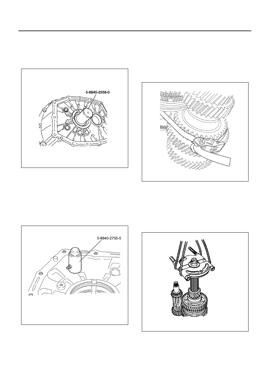
4. Use the installer (5-8840-2558-0) to press the oil

seal into the clutch housing.

Caution:
The lipped portion of the oil seal is easily broken. Exer-
cise care during the installation procedure.

5. Inspect the bearing outer race for wear and dam-

age. If wear or damage is present, the race must
be replaced.

6. Inspect the clutch housing bush for wear and dam-

age. If wear or damage is present, the bush must
be replaced.

7. Use the installer (5-8840-2755-0) to press the bush

into the clutch housing. Pay close attention to the
bush installation direction (refer to the illustration).

• Attach by crimping to secure at three points, but

avoid the grooved area and previous crimping
spots.

• Apply the second and subsequent bushing press-

es with the notch facing the clutch housing.

8. Attach the main shaft assembly, upper gear shaft

assembly, and countershaft assembly.
a. Tightly wrap belts such as lashing belts around

the main shaft assembly, countershaft assem-
bly, and upper gear shaft assembly at two or
more places to prevent the assemblies from
separating. Make sure that the upper gear shaft
does not fall when the assembly is suspended.

b. Secure the bearing remover to the main shaft

with a lock nut, then raise it with a hoisting ca-
ble. Spread the outer snap ring of the upper
gear shaft bearing, which is attached to the
clutch housing, and simultaneously install the
upper gear shaft assembly, main shaft assem-
bly, and countershaft assembly into the clutch
housing.

c. Set the outer snap ring of the upper gear shaft

bearing onto the clutch housing, spread it using
snap-ring pliers, and insert the upper gear shaft
bearing.

N7A0326E

N7A1104E

N7A1095E

N7A0356E

MANUAL TRANSMISSION (MZZ) 7B1-21

Notice:

• Be sure to verify that the snap ring is properly at-

tached.

• When suspending the shaft, maintain vertical

alignment to prevent the front oil seal from being
damaged, and work with care.

9. Install the magnet to the clutch housing.

10. Inspect the 3rd / 2nd shift arm bush for wear and

damage. If wear or damage is present, the bush
must be replaced.

11. Use the installer (5-8840-2755-0) to press the bush

into the clutch housing. Pay careful attention to di-
rection of installation and installation angle.

12. Caulk the bush at 3 locations (do not caulk near the

bush grooves).

13. Inspect the 1st / reverse shift arm bush for wear

and damage. If wear or damage is present, the
bush must be replaced.

14. Use the installer (5-8840-2755-0) to press the bush

into the clutch housing. Pay careful attention to di-
rection of installation and installation angle.

15. Caulk the bush at 3 locations (do not caulk near the

bush grooves).

16. Inspect the 4th / 5th shift arm bush for wear and

damage. If wear or damage is present, the bush
must be replaced.

17. Use the installer (5-8840-2755-0) to press the bush

into the clutch housing.

18. Caulk the bush at 3 locations (do not caulk near the

bush grooves). Pay careful attention to direction of
installation and installation angle.

19. Align the spring pin holes.

N7A1097E

N7A1109E

N7A1110E

7B1-22 MANUAL TRANSMISSION (MZZ)

20. Install the 1st / reverse and the 2nd / 3rd shift rod

(1) to the 1st / reverse and the 6th shift block (5),
the 2nd / 3rd shift arm (4), and the 1st / reverse shift
arm (2).

21. Use a hammer to drive the spring pins (3) (6) into

the holes.

Caution:
To avoid damaging other parts, place a round shaft at
the opposite end of the shift rod when installing the
spring pins.

22. Align the spring pin holes.
23. Install the 4th / 5th and the 6th shift rod (1) to the

4th / 5th shift arm (3), the 1st / reverse and the 6th
shift block (2).

24. Use a hammer to drive the spring pins (4) into the

holes.

Caution:
To avoid damaging other parts, place a round shaft at
the opposite end of the shift rod when installing the
spring pins.

25. Apply Three Bond 1215 to the fitting surfaces of the

transmission case and the clutch housing.

• Remove moisture and oil from the fitting surface

prior to application. Set the bead diameter to great-
er than 2 mm (0.078 in) and make it even all
around.

26. Install the clutch housing to the transmission case.

Tighten the bolts to the specified torque.

Tighten:
Bolts to 46 N

⋅m (4.7 kg⋅m / 34 lb⋅ft)

27. Install the bearing rear outer race to the transmis-

sion case.

28. Install the snap ring to the 4th / 5th and the 6th gear

shift rod.

Notice:
If a snap ring is deformed or damaged, replace it with a
new one and verify that it is attached properly.

N7A1166E

N7A1167E

MANUAL TRANSMISSION (MZZ) 7B1-23

29. Attaching the countershim

a. Put the gear into neutral.
b. Set the transmission assembly with the hous-

ing at the bottom.

c. Break in the taper roller bearing by rotating the

countershaft at least 30 times.

d. Selecting a countershim

• Measure the depth between the rear most

surface of the transmission housing and the
outer wheel surfaces of the countershaft
rear bearing. Take three measurements at
120-degree intervals, and calculate the av-
erage.

• Select the shim with the appropriate thick-

ness from the table below.

30. Install the snap ring (rear outer) to the main shaft

rear bearing.

31. Apply engine oil (5W-30) to the needle bearing.
32. Install the reverse idle gear together with the nee-

dle bearing and the oil slinger.

33. Install the reverse idle shaft.

• The arrow indicates the front of the transmission.

Measured depth mm (in)

Shim thickness mm (in)

2.13 — 2.19

 (0.084 — 0.086)

1.98 (0.078)

N7A0353E

N7A1115E

2.07 — 2.13

(0.081 — 0.084)

1.92 (0.076)

2.01 — 2.07

(0.079 — 0.081)

1.88 (0.074)

1.95 — 2.01

(0.077 — 0.079)

1.80 (0.071)

1.89 — 1.95

(0.074 — 0.077)

1.74 (0.069)

1.83 — 1.89

(0.072 — 0.074)

1.68 (0.066)

1.77 — 1.83

(0.070 — 0.072)

1.62 (0.064)

1.71 — 1.77

(0.067 — 0.070)

1.58 (0.062)

1.65 — 1.71

(0.065 — 0.067)

1.50 (0.059)

1.59 — 1.65

(0.063 — 0.065)

1.44 (0.057)

1.53 — 1.59

(0.060 — 0.063)

1.38 (0.054)

1.47 — 1.53

(0.058 — 0.060)

1.32 (0.052)

1.41 — 1.47

(0.056 — 0.058)

1.26 (0.050)

1.35 — 1.41

(0.053 — 0.056)

1.20 (0.047)

Measured depth mm (in)

Shim thickness mm (in)

N7A0338E


Content   ..  872  873  874  875   ..