Isuzu N-Series. Service manual - part 809


  Index      Isuzu     Isuzu N-Series - service and repair manual


Search            


Content   ..  807  808  809  810   ..


Isuzu N-Series. Service manual - part 809


7B-6 MANUAL TRANSMISSION (MSB)

Installation

1. Vehicle Speed Sensor Driven Gear Assembly

Tighten:
Fixing bolt to 15 N

⋅m (1.5 kg⋅m / 11 lb⋅ft)

2. Vehicle Speed Sensor with Key Rod

Tighten:
Fixing bolt to 25 N

⋅m (2.5 kg⋅m / 18 lb⋅ft)

3. Wiring Connector

Back-up Light Switch and Neutral Switch
Replacement

Removal

1. Wiring Connector
2. Switch

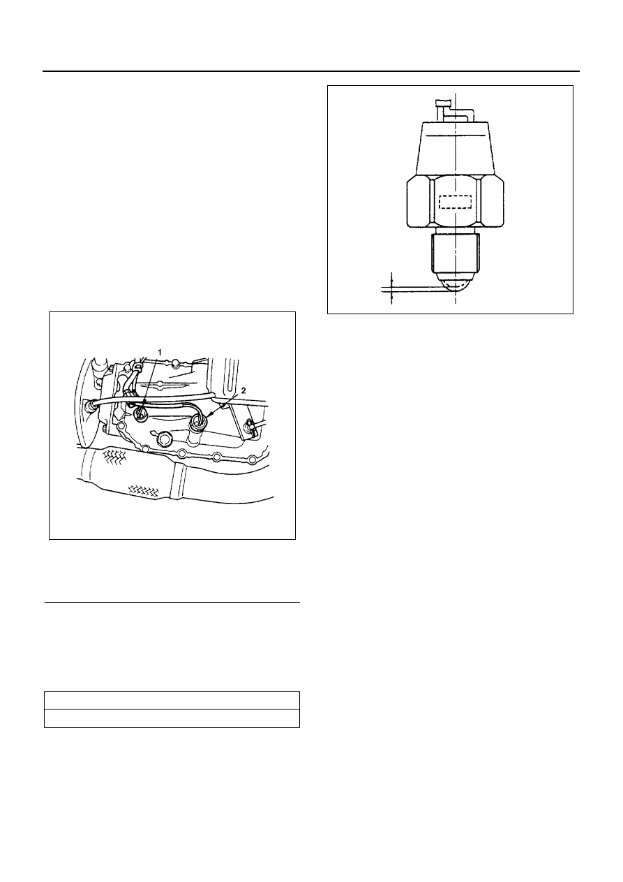
Inspection and Repair

• When there is continuity between the terminals in

the condition as it is, and when the continuity be-
tween the terminals is turned off by pressing the
ball of the switch, the switch is normal.

Installation

1. Switch

• Apply liquid gasket (Three Bond 1141 or equiv-

alent) to the switch’s threaded portion to pre-
vent oil leakage, and install the switch to the
control box.

• Color of connector

Back-up Light Switch: Brown
Neutral Switch: Gray

Tighten:
Switch to 34 N

⋅m (3.5 kg⋅m / 25 lb⋅ft)

2. Wiring Connector

Rear Oil Seal Replacement

Removal

• Raise vehicle and support with suitable safety

stands.

1. Propeller Shaft

• Put a reference mark (1) on the flange yoke and

the parking brake drum.

Legend

1. Back-up light switch
2. Neutral switch

Switch Operating Stroke

mm (in)

0.93 (0.037)

N7A0042E

N7A0043E

MANUAL TRANSMISSION (MSB) 7B-7

• Disconnect the propeller shaft at flange yoke.
• Put aside the propeller shaft and tie it to the

frame so it does not interfere with servicing
work.

2. Parking Brake Drum

• Remove the screw and the adjust hole cover.
• It may be necessary to back off the shoe adjust-

er.

3. Lock Nut

• Make sure to raise the caulking of the coupling

driver lock nut, then remove the lock nut.

• Use the handle to remove the lock nut.

Handle: 5-8840-2043-0

4. Coupling Driver

• Remove the coupling driver using the universal

puller.
Universal Puller: 5-8840-2027-0

• Remove the conical washer and the O-ring.

5. Parking Brake Assembly

N7A0044E

N7A0045E

N7A0046E

N7A0047E

7B-8 MANUAL TRANSMISSION (MSB)

6. Oil Seal

• Use the screwdriver to remove the oil seal from

the rear cover.

Caution:
Take care not to damage the sealing seat of the rear
cover.

Installation

1. Oil Seal

• Apply engine oil to the new oil seal outer cir-

cumference and apply multi-purpose grease to
the oil seal lip.

• Use the oil seal installer to install the oil seal to

the rear cover.
Oil Seal Installer: 5-8840-2242-0

2. Parking Brake Assembly

Tighten:

• Parking brake bolts to 25 N

⋅m (2.5 kg⋅m / 18 lb⋅ft)

• Parking brake nut to 113 N

⋅m (11.5 kg⋅m / 83 lb⋅ft)

3. Coupling Driver
4. Lock Nut

• Install the O-ring and the conical washer.

The conical washer is to be set up with its iden-
tification groove to the nut side.

Caution:
Do not reuse the lock nut.

• Apply the engine oil to the setting face of the

new lock nut and tighten it up to the specified
torque.
Handle: 5-8840-2043-0

Tighten:
Lock nut to 226 N

⋅m (23.0 kg⋅m / 166 lb⋅ft)

• Align the lock nut with the V-shaped groove at

the tip of the main shaft, and caulk the nut lip
portion by using a chisel.
(Round edge approximately 1 mm (0.04 in) 

×

60

°).

• As shown in the illustration, be sure to caulk the

nut lip so that the clearance between the V-
shaped groove portion at the tip of the main
shaft and the caulked up lip (A) is less than 1.5
mm (0.06 in), and the caulking length (B) is 5
mm (0.2 in) or more.

Caution:
Be sure to confirm that there is no crack at the caulked
portion of the end nut after caulking.

N7A0048E

N7A0049E

N7A0048E

MANUAL TRANSMISSION (MSB) 7B-9

5. Parking Brake Drum

• Adjust the parking brake after installation.

1) Rotate the brake drum to align the adjust hole

with the adjuster.

2) Move the camshaft lever from side to side sev-

eral times to center the brake shoes.

3) Insert a screwdriver into the hole and rotate the

adjuster by pushing it upward until the shoes
drag on the drum.

4) Back off the adjuster 30 notches.

• Install the adjust hole cover.

Tighten:
Adjust hole cover bolt to 8 N

⋅m (0.8 kg⋅m / 69 lb⋅in)

6. Propeller Shaft

• Line up reference mark (1).

Tighten:
Propeller shaft bolt to 66 N

⋅m (6.7 kg⋅m / 48 lb⋅ft)

• Remove the safety stands.

Transmission Assembly Replacement

Removal

• Raise vehicle and support with suitable safety

stands.

1. Propeller Shaft

• Put a reference mark (1) on the flange yoke and

the parking brake drum.

N7A0050E

N7A0045E

N7A0044E


Content   ..  807  808  809  810   ..