Isuzu N-Series. Service manual - part 808


  Index      Isuzu     Isuzu N-Series - service and repair manual


Search            


Content   ..  806  807  808  809   ..


Isuzu N-Series. Service manual - part 808


7B-2 MANUAL TRANSMISSION (MSB)

GENERAL DESCRIPTION

For MSB model transmission, a forward 5-shift all syn-
chromesh type and a backward 1-shift constant mesh
type transmission are employed.
The transmission case is made of a high rigidity cast
iron, and the front cover integral with the clutch housing
is made of aluminum die-cast. An aluminum die-cast
control box containing a gear shift and gear select
mechanism is installed on the right side of the transmis-
sion case. A window for power take-off is also provided
on the left side.
For all the gears, helical gears are employed to
reduce noises.

The synchromesh mechanism that employs balking
rings use block rings of special brass to obtain improved
synchromesh performance.
With the main shaft screwed up at the rear, ball bearings
are employed for the bearings on both sides of the main
shaft and the counter shaft, and needle roller bearings
employed for the bearings at the tip end of the main
shaft and also for those of the 1st gear, 2nd gear, 3rd
gear and reverse gear to secure improved durability and
reduced noises.
Furthermore, with the anti-lash mechanism employed
for the engagement of the top gear with the counter
gear, fine-pitch gears are also employed for the 4th gear
and the 5th gear to reduce noises.
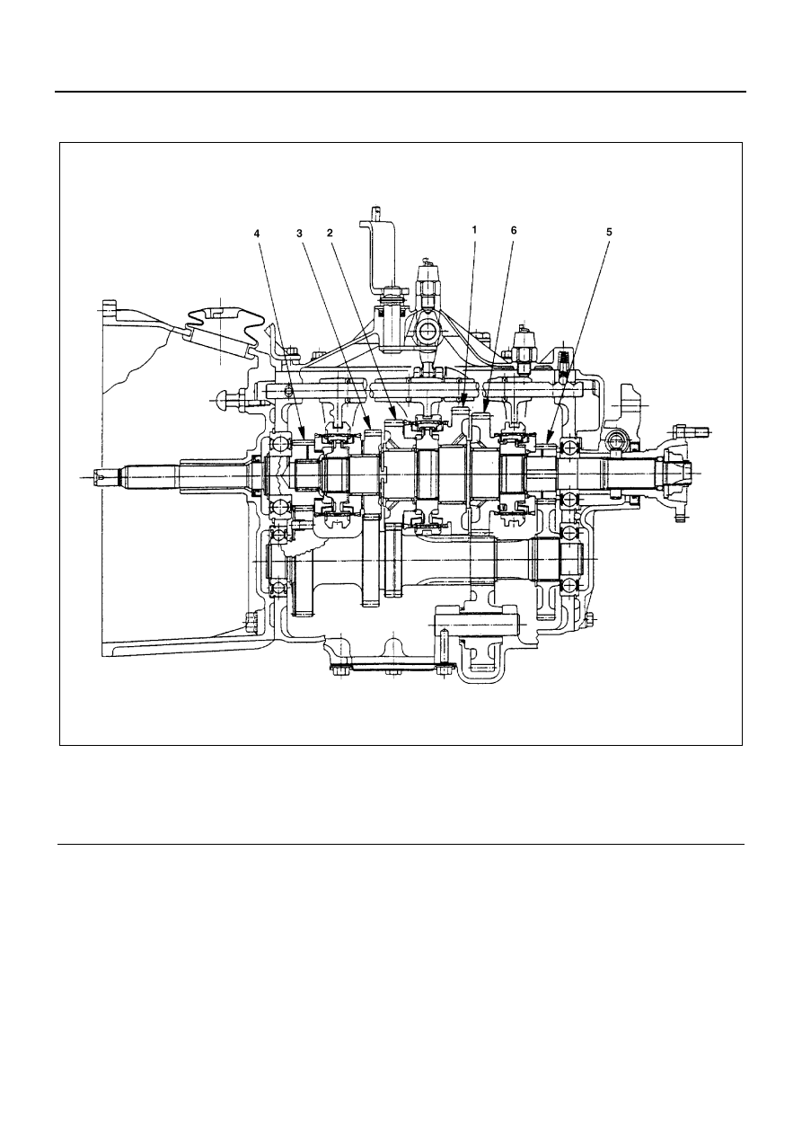
Legend

1. 1st

4. 4th

2. 2nd

5. 5th

3. 3rd

6. Rev.

N7A0035E

MANUAL TRANSMISSION (MSB) 7B-3

ON-VEHICLE SERVICE

Change Lever Assembly Replacement

Removal

1. Change Lever Knob
2. Cover Assembly

• Remove the fixing screw and three clips.

3. Shift Cable and Select Cable

• Disconnect the cables from the change lever.
• Remove the clips and disconnect the cables

from bracket.

4. Change Lever Assembly

Installation

1. Change Lever Assembly
2. Shift Cable and Select Cable

When connecting the shift cable and the select ca-
ble to the change lever, adjust the cable.

Refer to “SERVICING: GEAR CONTROL CABLE
ADJUSTMENT” given previously in this section.

3. Cover Assembly
4. Change Lever Knob

Gear Control Cable Replacement

Removal

1. Change Lever Knob
2. Cover Assembly
3. Shift Cable and Select Cable

1) Disconnect the shift and select cables from

change lever.

2) Remove the clips and disconnect the cables

from change lever bracket.

3) Remove the grommet retainer, grommet seal

and grommet.

4) Tilt the cab.

Legend

1. Knob
2. Cover assembly
3. Change lever
4. Shift cable
5. Clip
6. Snap pin
7. Select cable

N7A0036E

N7A0037E

7B-4 MANUAL TRANSMISSION (MSB)

5) Disconnect the shift cable and the select cable

on the transmission side.

6) Remove the clips and disconnect the shift ca-

ble and the select cable from the bracket.

7) Remove the clips that fix the cables to the

frames.

8) Remove the shift and select cable assemblies.

Inspection and Repair

Check the cables for any deformation, damage or rust,
and also check the sliding portion for any abnormal con-
dition.
When there is any abnormal condition, replace it with a
new one.

Installation

1. Shift Cable and Select Cable

1) Install the shift cable and the select cable tem-

porarily.

Caution:
Never bend the cables to radius less than 450 mm (18
in) unless it is necessary to do so for wiring purposes.
And never bend the cables to radius less than 180 mm
(7 in) even during wiring. Install the cables carefully with-
out unnecessary twisting the cable boots.

2) Connect the shift cable and the select cable to

the transmission.

3) Fasten the cables with clips to the brackets on

the transmission side.

4) Fasten the cables with clips to the change lever

bracket.

5) Fasten the cables with clips to the frames. At-

this time, take care that the select cable comes
above the shift cable.

6) Install the grommet, grommet seal and grom-

met retainer.

7) When connecting the shift cable and the select

cable to the change lever, adjust the cables.
Refer to “SERVICING: GEAR CONTROL CA-
BLE ADJUSTMENT” given previously in this
section.

2. Cover Assembly
3. Change Lever Knob

Legend

1. Knob
2. Cover assembly
3. Change lever
4. Shift cable
5. Select cable
6. Grommet retainer
7. Grommet seal
8. Grommet

Legend

4. Shift cable
5. Select cable
9. Snap pin

10. Clip

N7A0038E

MANUAL TRANSMISSION (MSB) 7B-5

Vehicle Speed Sensor Driven Gear Re-
placement

Removal

1. Wiring Connector

2. Vehicle Speed Sensor with Key Rod
3. Vehicle Speed Sensor Driven Gear Assembly

• Remove the fixing bolt.
• Remove the driven gear assembly.

N7A0039E

N7A0040E

Legend

1. Key rod
2. Vehicle speed sensor
3. Bushing
4. O-ring
5. Driven gear

N7A0041E


Content   ..  806  807  808  809   ..