Isuzu N-Series. Service manual - part 695


  Index      Isuzu     Isuzu N-Series - service and repair manual


Search            


Content   ..  693  694  695  696   ..


Isuzu N-Series. Service manual - part 695


6E-202    Engine Control System (4HK1) 
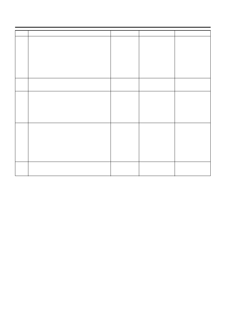
13

1.

Turn OFF the ignition.

2.

Disconnect the ECM harness connector.

3.

Inspect for an intermittent and for a poor
connection on the starter cut relay circuit at
the harness connector of the ECM (pin 14 of
J-191 connector).

4.

Repair the connection(s) as necessary.

Did you find and correct the condition?

Go to Step 16

Go to Step 15

14

Replace the starter cut relay.

Did you complete the replacement?

Go to Step 16

15

Important:
Replacement ECM must be programmed.

Replace the ECM. Refer to Engine Control Module
(ECM) Replacement / Fuel Injector ID Code Data
Programming in this section.

Did you complete the replacement?

Go to Step 16

16

1.

Reconnect all previously disconnected fuse,
relay or harness connector(s).

2.

Clear the DTCs with the Tech 2.

3.

Turn OFF the ignition for 30 seconds.

4.

Turn ON the ignition for 5 seconds.

5.

Start the engine.

Did the DTC fail this ignition?

Go to Step 2

Go to Step 17

17

Observe the DTC Information with the Tech 2.

Are there any DTCs that you have not diagnosed?

Go to Diagnostic 

Trouble Code (DTC) 

List

System OK

Step

Action

Value(s)

Yes

No

 Engine Control System (4HK1)    6E-203

P0650 (Flash Code 77)

Circuit Description
The malfunction indicator lamp (MIL) is located on the
instrument panel cluster (IPC). The MIL informs the
driver that an emission system or a performance
related fault has occurred and that the engine control
system requires service. The engine control module
(ECM) monitors the MIL control circuit for conditions
that are incorrect for the commanded state of the MIL.
For example, a failure condition exists if the ECM
detects low voltage when the MIL is commanded OFF,
or high voltage when the MIL is commanded ON. If the
ECM detects an improper voltage on the MIL control
circuit, this DTC will set.

Condition for Running the DTC

• The ignition switch is ON.
• The ignition voltage is more than 18 volts.

Condition for Setting the DTC
Either of following condition is met:

• The ECM detects a low voltage condition on the

MIL control circuit when the indicator is
commanded OFF for longer than 3 seconds.

• The ECM detects a high voltage condition on the

MIL control circuit when the indicator is
commanded ON for longer than 3 seconds.

Action Taken When the DTC Sets

• The ECM does not illuminate the MIL when the

diagnostic runs and fails.

Condition for Clearing the DTC

• A current DTC clears when the diagnostic runs and

does not fail at next driving cycle.

• A history DTC clears after 20 consecutive driving

cycles without a fault. Or clear with the Tech 2 or
accelerator pedal operation.

Diagnostic Aid

• If an intermittent condition is suspected, refer to

Intermittent Conditions in this section.

DTC P0650 (Flash Code 77)
Schematic Reference: 
Engine Controls Schematics
Connector End View Reference: Engine Controls
Connector End Views or Engine Control Module (ECM)
Connector End Views

Step

Action

Value(s)

Yes

No

1

Did you perform the Diagnostic System Check –
Engine Controls?

Go to Step 2

Go to Diagnostic 

System Check – 

Engine Controls

2

1.

Verify whether the instrument cluster is
operational. If the instrument panel cluster
(IPC) is completely inoperative, refer to
Diagnostic System Check.

2.

Turn OFF the ignition for 30 seconds.

3.

Turn ON the ignition for 30 seconds while
observing the Diagnostic Trouble Code (DTC)
Information with the Tech 2.

Does the DTC fail this ignition?

Go to Step 3

Go to Diagnostic 

Aids

3

1.

Turn OFF the ignition.

2.

Inspect the Meter (10A) fuse in the glove box.

Is the Meter (10A) fuse open?

Go to Step 4

Go to Step 5

4

Replace the Meter (10A) fuse. If the fuse continues
to open, repair the short to ground on one of the
circuits that is fed by the Meter (10A) fuse or
replace the shorted attached component fed by the
Meter (10A) fuse.

Did you complete the repair?

Go to Step 19

5

1.

Turn OFF the ignition.

2.

Disconnect the engine control module (ECM)
J-191 harness connector.

3.

Turn ON the ignition, with the engine OFF.

Is the malfunction indicator lamp (MIL) OFF?

Go to Step 6

Go to Step 13

6E-204    Engine Control System (4HK1) 

6

1.

Remove the Meter (10A) fuse that supplies
voltage to the MIL.

2.

Turn ON the ignition, with the engine OFF.

3.

Measure the voltage from the MIL control
circuit in the ECM harness connector (pin 6 of
J-191 connector) to a good ground.

Is the voltage less than the specified value?

1 volt

Go to Step 7

Go to Step 14

7

1.

Turn OFF the ignition.

2.

Install the Meter (10A) fuse that supplies
ignition voltage to the MIL.

3.

Turn ON the ignition, with the engine OFF.

4.

Connect a 3-amp fused jumper wire between
the MIL control circuit of the ECM harness
connector (pin 6 of J-191 connector) and a
known good ground.

Is the MIL illuminated?

Go to Step 12

Go to Step 8

8

1.

Turn OFF the ignition.

2.

Remove the IPC.

3.

Remove the MIL bulb from the IPC.

Is the MIL bulb burned out?

Go to Step 16

Go to Step 9

9

1.

Connect a test lamp between the MIL ignition
voltage circuit of the IPC harness connector
(pin 18 of B-51 connector) and a known good
ground.

2.

Turn ON the ignition, with the engine OFF.

Does the test lamp illuminate?

Go to Step 10

Go to Step 15

10

1.

Test the MIL control circuit between the ECM
(pin 6 of J-191 connector) and the IPC (pin 5
or 13 of B-51 connector) for an open circuit or
high resistance.

2.

Repair the circuit(s) as necessary.

Did you find and correct the condition?

Go to Step 19

Go to Step 11

11

1.

Turn OFF the ignition.

2.

Inspect for an intermittent and for poor
connections at the harness connector of the
IPC (pins 5 or 13 and 18 of B-51 connector).

3.

Repair the connection(s) as necessary.

Did you find and correct the condition?

Go to Step 19

Go to Step 17

12

1.

Turn OFF the ignition.

2.

Disconnect the ECM harness connector.

3.

Inspect for an intermittent and for a poor
connection on the MIL control circuit at the
harness connector of the ECM (pin 6 of J-191
connector).

4.

Repair the connection(s) as necessary.

Did you find and correct the condition?

Go to Step 19

Go to Step 18

13

Repair the short to ground on the control circuit of
the MIL between the ECM (pin 6 of J-191
connector) and the IPC (pin 5 or 13 of B-51
connector).

Did you complete the repair?

Go to Step 19

Step

Action

Value(s)

Yes

No

 Engine Control System (4HK1)    6E-205

14

Repair the short to battery or ignition voltage on the
control circuit of the MIL between the ECM (pin 6 of
J-191 connector) and the IPC (pin 5 or 13 of B-51
connector).

Did you complete the repair?

Go to Step 19

15

Repair the open or high resistance on the ignition
voltage circuit of the MIL between the Meter (10A)
fuse and the IPC (pin 18 of B-51 connector).

Did you complete the repair?

Go to Step 19

16

Replace the MIL bulb.

Did you compete the replacement?

Go to Step 19

17

Repair or replace the IPC.

Did you complete the repair or replacement?

Go to Step 19

18

Important:
Replacement ECM must be programmed.

Replace the ECM. Refer to Engine Control Module
(ECM) Replacement / Fuel Injector ID Code Data
Programming in this section.

Did you complete the replacement?

Go to Step 19

19

1.

Reconnect all previously disconnected fuse or
harness connector(s).

2.

Clear the DTCs with the Tech 2.

3.

Turn OFF the ignition for 30 seconds.

4.

Turn ON the ignition for 30 seconds while
observing the DTC Information with the Tech
2.

Did the DTC fail this ignition?

Go to Step 3

Go to Step 20

20

Observe the DTC Information with the Tech 2.

Are there any DTCs that you have not diagnosed?

Go to Diagnostic 

Trouble Code (DTC) 

List

System OK

Step

Action

Value(s)

Yes

No


Content   ..  693  694  695  696   ..