Isuzu N-Series. Service manual - part 618


  Index      Isuzu     Isuzu N-Series - service and repair manual


Search            


Content   ..  616  617  618  619   ..


Isuzu N-Series. Service manual - part 618


6C-42 ENGINE FUEL

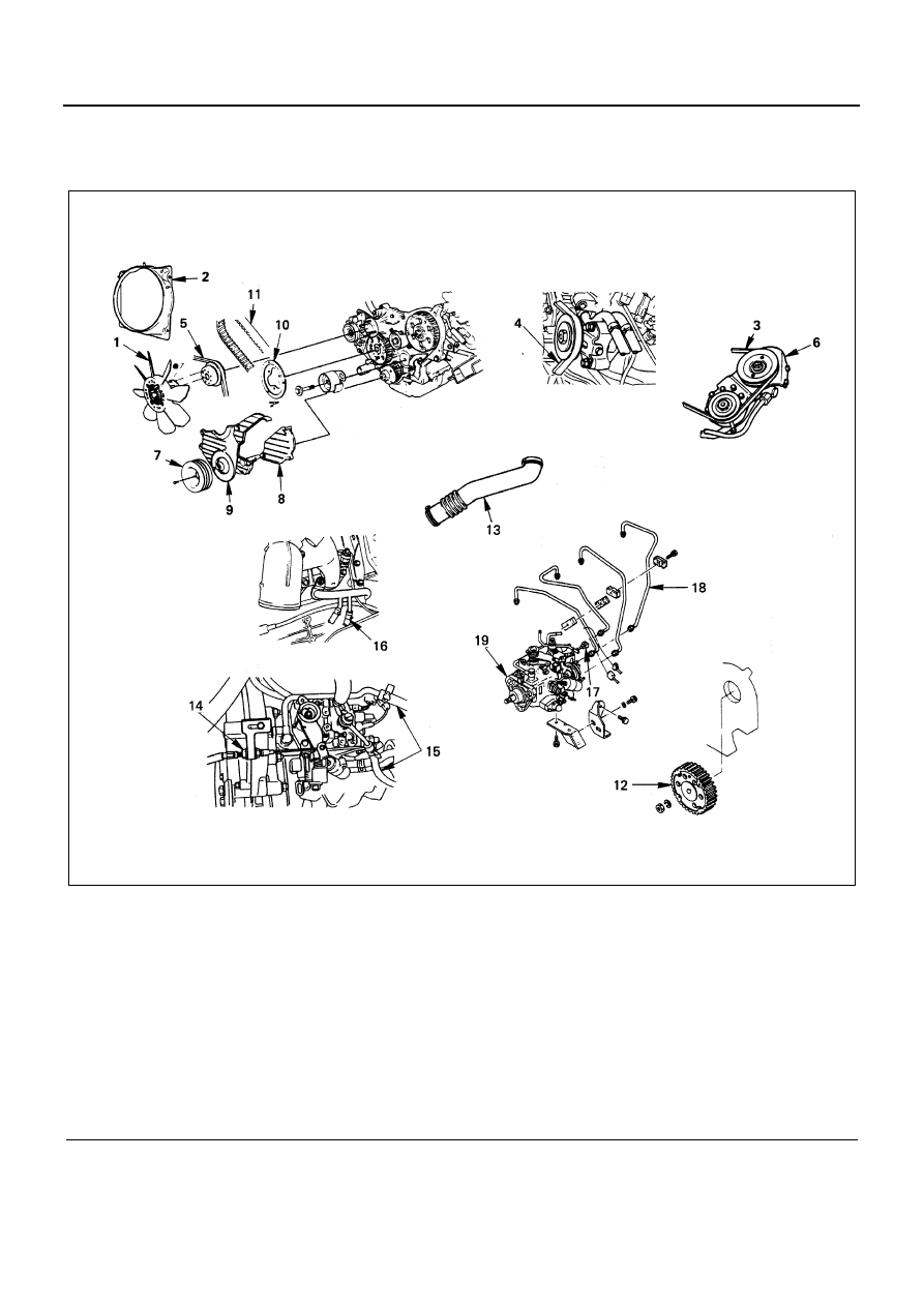
INJECTION PUMP ASSEMBLY (4JG2 Belt Drive Type)

Component

Legend

1. Cooling fan assembly

11. Timing belt

2. Fan shroud

12. Injection pump timing pulley

3. Power steering pump drive belt

13. Air intake duct

4. A/C compressor drive belt

14. Injection pump control cable

5. AC generator drive belt

15. Fuel hose

6. Power steering pump & bracket assembly

16. CSD water hose

7. Crankshaft damper pulley

17. Injection pump harness

8. Timing pulley upper cover

18. Injection pipe

9. Timing pulley lower cover

19. Injection pump assembly

10. Flange; Camshaft pulley

N6A3767E

ENGINE FUEL 6C-43

Removal

Preparation:

• Disconnect battery ground cable.
• Drain coolant.

1. Cooling Fan Assembly

• Remove clamp nut, and remove cooling fan as-

sembly, distant pipe, and fan pulley.

2. Fan Shroud

• Remove reservoir tank hose and fan shroud.

3. Power Steering Pump Drive Belt (P/S Model)

• Loosen power steering pump idle pulley lock nut

and adjust bolt, and remove the drive belt.

4. A/C Compressor Drive Belt (A/C Model)

• Loosen A/C compressor idler pulley lock nut (1),

adjust bolt (2), and remove the drive belt.

5. AC Generator Drive Belt

• Loosen AC generator mounting bolt (under side)

and adjust plate lock bolt (1), and remove the drive
belt.

6. Power Steering Pump & Bracket Assembly (P/S

Model)

• Loosen power steering oil pipe bracket (1) and clip

(2).

• Remove P/S pump bracket assembly and hang the

P/S pump bracket assembly.

7. Crankshaft Dumper Pulley

N6A3223E

N6A3698E

Legend

1. Bracket
2. Clip
3. Lock nut
4. P/S pump bracket

N6A3699E

N6A3771E

6C-44 ENGINE FUEL

8. Timing Pulley Upper Cover (1)
9. Timing Pulley Lower Cover (2)

10. Flange; Camshaft Pulley

11. Timing Belt

• Prepare a fixing bolt (M8 

× 40, P=1.25).

• Turn crankshaft timing pulley in the normal direct

pulley side mark to timing pulley housing side
mark.

• Make sure that the camshaft pulley and injection

timing pulley fixing bolt holes are set to each other.
Then fit in a fixing bolt and lightly tighten.

• No. 1 cylinder should be at top dead center.

If the fixing bolt holes are not set (No. 4 cylinder is
at top dead center) give another turn.

• Remove tensioner and timing belt.

Warning:

WARNING:

• IF CRANKSHAFT AND CAMSHAFT ARE

TURNED WITH TIMING BELT BEING NOT
MOUNTED, PISTON AND VALVE WILL INTER-
FERE WITH EACH OTHER. THEREFORE, THE
SHAFTS MUST NOT BE TURNED.

N6A3159E

N6A3773E

N6A3774E

N6A3775E

ENGINE FUEL 6C-45

12. Injection Pump Timing Pulley

• Install the stopper bolt (1) to the timing pulley to

prevent it from turning.

• Use the timing pulley puller (2) to remove the injec-

tion pump timing pulley.
Timing Pulley Puller: 5-8840-0086-0

• Remove the stopper bolt.

13. Air Intake Duct
14. Injection Pump Control Cable

• Remove the control cable bracket bolt and remove

the control lever side.

15. Fuel Hose

• Disconnect the fuel feed hose and fuel return hose.

16. CSD Water Hose
17. Injection Pump Harness
18. Injection Pipe
19. Injection Pump Assembly

• Remove the pump bracket bolt engine side.
• Remove the adjust lock bolt.
• Remove the injection pump fixing bolt and take out

injection pump.

N6A3704E

N6A3777E

N6A3778E

N6A3779E


Content   ..  616  617  618  619   ..