Isuzu N-Series. Service manual - part 616


  Index      Isuzu     Isuzu N-Series - service and repair manual


Search            


Content   ..  614  615  616  617   ..


Isuzu N-Series. Service manual - part 616


6C-34 ENGINE FUEL

Removal

Preparation:

• Disconnect battery ground cable.
• Drain coolant.

1. Cooling Fan Assembly

• Remove clamp nut, and remove cooling fan as-

sembly, distant pipe, and fan pulley.

2. Fan Shroud
3. Power Steering Pump Drive Belt (P/S Model)

• Loosen power steering pump mounting bolt and

adjust bolt, and remove the drive belt.

4. A/C Compressor Drive Belt (A/C Model)

• Loosen A/C compressor idler pulley lock nut, ad-

just bolt and remove the drive belt.

5. AC Generator Drive Belt

• Loosen AC generator mounting bolt (under side)

and adjust plate lock bolt, and remove the drive
belt.

6. Noise Shield Cover
7. Noise Cover Spacer
8. Air Intake Duct
9. Injection Pump Control Cable

• Remove the control cable bracket bolt and remove

the control lever side.

10. Fuel Hose

• Disconnect the fuel feed hose and fuel return hose.

11. CSD (Cold Starting Device) Water Hose

• Disconnect the water hose from injection pump

side.

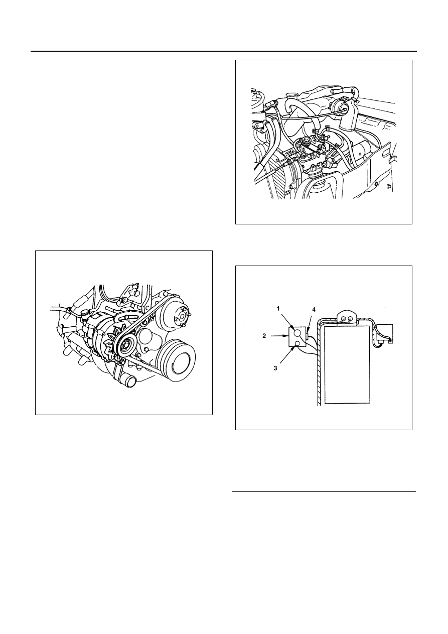
12. Injection Pump Harness

• Remove the tachometer sensor (with tachometer),

CSD solenoid, fuel cut solenoid.

13. Injection Pipe

• Release pipe clip.
• Remove the flare nut on the pump side.
• Remove the flare nut on the injection nozzle side,

and remove the injection pipe.

Caution:

• Be sure to plug the injection nozzle holder and de-

livery holder to prevent the entry of foreign matter.

14. Injection Pump Assembly

• Remove pump mounting nut.

N6A3439E

Legend

1. CSD solenoid
2. Injection pump
3. Fuel cut solenoid
4. Tachometer sensor

N6A3440E

N6A3441E

ENGINE FUEL 6C-35

• Loosen injection pump rear bracket adjuster lock

bolt.

• Remove the mounting bolt on the engine side, and

pull out the pump from the engine.

Notice:
Plug the injection pump delivery holder parts with the
shipping caps (or the equivalent) to prevent the entry of
foreign materials.

Installation

1. Injection Pump Assembly

1) Timing gear case a camshaft timing gear side c

injection pump timing gear side check hold cov-
er.

2) Turn the crankshaft clockwise to see the TDC

mark of the crank pulley to the pointer, and then
bring the No. 1 cylinder to the TDC on the com-
pression stroke.

3) Look in through the check hole on the crank-

shaft timing gear side and check to see if the
“O” mark on the timing gear is in line with the
pointer of the check hole.

4) In the condition above with the injection pump

gear mark “O” set to the pointer of the check
hole, install the injection pump assembly.

• Install the injection pump fixing bolts and tighten

them to the specified torque.

Tighten:
Pump Bolts to 15 N

⋅m (1.5 kg⋅m/11 lb⋅ft)

2. Injection Pipe

• Connect the pump side and nozzle side of the pipe,

and tighten securely.

• Install clip where it was.

Tighten:
Sleeve Nut to 29 N

⋅m (3.0 kg⋅m/22 lb⋅ft)

N6A3442E

N6A3443E

Legend

A. Camshaft gear
B. Injection pump gear

N6A3444E

6C-36 ENGINE FUEL

3. Injection Pump Harness

• Mount engine harness and connect it to switches.

4. CSD Water Hose

• Connect the water hose and tighten clip securely.

5. Fuel Hose

• Connect the fuel feed hose and fuel return hose.
• Connect the leak off hose.

6. Injection Pump Control Cable

1) Install the control wire to the engine control le-

ver.

2) Hold the accelerator lever in the fully closed po-

sition and stretch the control cable in the direc-
tion indicated by the arrow to remove any slack.

3) Tighten the accelerator cable bracket bolt.

7. Air Intake Duct
8. Noise Cover Spacer
9. Noise Shield Cover

10. AC Generator Drive Belt

• Install AC generator drive belt and adjust belt ten-

sion.

• Depress the drive belt mid-portion with a 98 N (10

kg/22 lb) force.

N6A3781E

N6A3445E

Drive Belt Deflection

mm (in)

8 (0.31) — 12 (0.47)

N6A3368E

N6A3447E

ENGINE FUEL 6C-37

4JG2

4JB1

• Install fixing bolt and tighten bolts to the specified

torque.

Tighten:

• Generator Fixing Bolt to 40 N

⋅m (4.1 kg⋅m/30 lb⋅ft)

• Adjust Plate Fixing Bolt to 19 N

⋅m (1.9 kg⋅m/14 lb⋅ft)

11. A/C Compressor Drive Belt (A/C Model)

• Install A/C compressor drive belt and adjust belt

tension.

• Depress the drive belt mid-portion with a 98N (10

kg/22 lb) force.

• Tighten the idler lock nut to the specified torque.

Tighten:
27 N

⋅m (2.8 kg⋅m/20 lb⋅ft)

12. Power Steering Pump Drive Belt (P/S Model)

• Install P/S pump drive belt and adjust belt tension.
• Depress the drive belt mid-portion with a 98 N (10

kg/ 22 lb) force.

• Tighten the idler lock nut to the specified torque.

Tighten:
27 N

⋅m (2.8 kg⋅m/20 lb⋅ft)

13. Fan Shroud

• Install the fan shroud and reservoir tank hose.

14. Cooling Fan Assembly

• Mount fan pulley, distance piece, and cooling fan

assembly (in this order) on the water pump, and
tighten to the specified torque.

Tighten:
8 N

⋅m (0.8 kg⋅m/69 lb⋅ft)

• Connect battery ground cable.
• Pour coolant.

Legend

1. A/C compressor drive belt
2. P/S oil pump drive belt
3. AC generator fan pulley drive belt

Legend

1. A/C compressor drive belt & P/S pump drive 

belt

2. AC generator & fan pulley drive belt

N6A3297E

N6A3295E

Drive Belt Deflection

mm (in)

8 (0.31) — 12 (0.47)

Drive Belt Deflection

mm (in)

8 (0.31) — 12 (0.47)

N6A3379E


Content   ..  614  615  616  617   ..