Isuzu N-Series. Service manual - part 607


  Index      Isuzu     Isuzu N-Series - service and repair manual


Search            


Content   ..  605  606  607  608   ..


Isuzu N-Series. Service manual - part 607


6B-14 ENGINE COOLING

• Remove the radiator valve and check a negative

pressure valve as the center of the valve seat side.
If the negative pressure valve does not work
smoothly, clean or replace the radiator valve.

Tighten:
Radiator valve to 6 N

⋅m (0.6 kg⋅m/4 lb⋅ft)

• Conduct cooling system leakage check after rein-

stalling the radiator valve.

Radiator Core

• Deformed radiator fins could reduce radiation ef-

fects, resulting in overheat. Straighten the fins. In
such a case, take care not to damage the fin roots. 

• Remove dust and other foreign materials.

Flushing the Radiator

• Wash the inside of radiator and the coolant pas-

sage with water and neutral detergent. Remove all
scales and rust.

Checking for Coolant Leakage

• Clog up the reservoir tank hose carefully and check

the cooling system for leakage with a radiator cap
tester by applying an air pressure of 147 kPa (1.5
kg/cm

2

 /21 psi) from filler neck to inside the radia-

tor.

• As the radiator upper tank is provided with a valve,

the pressure fails to rise higher than the valve
opening pressure unless the hose is clogged up.

Installation

1. Radiator Assembly

• Install the radiator.

2. Cushion Rubber

• Install cushion rubbers on both sides of radiator

bottom.

• Install radiator assembly with hose, taking care not

to damage the radiator core by a fan blade.

3. Condenser
4. Radiator Stay

5. Air Intake Duct

• Connect the duct and tighten clip securely.

6. Radiator Hose

• Connect inlet hose and outlet hose to the engine.
• Connect battery ground cable.
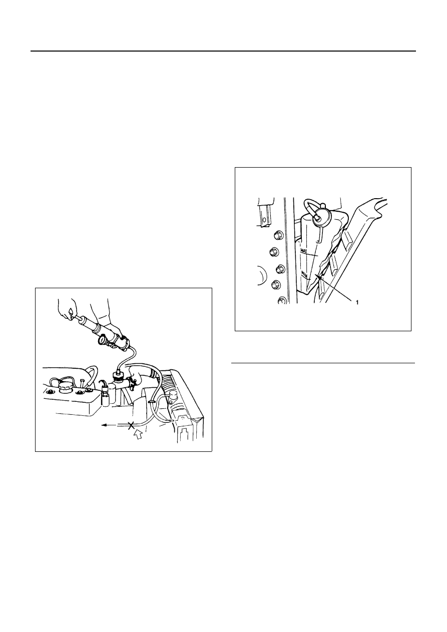
• Pour coolant up to filler neck of radiator, and up to

MAX mark of reservoir tank.

7. Reservoir Tank Hose & Bypass Hose

• Start engine to warm up, and check for coolant lev-

el.

N6A3389E

Legend

1. Reservoir tank

N6A3390E

ENGINE COOLING 6B-15

DRIVE BELT ADJUSTMENT

Component

Legend

A. AC, Generator cooling fan

C. A/C compressor P/S oil pump

B. A/C compressor P/S oil pump

1. A/C compressor

8. Cooling fan pulley

2. Idler pulley

9. Crank pulley

3. Adjust lock nut

10. P/S oil pump

4. Adjust plate

11. Adjust bolt

5. Adjust bolt

12. Idler pulley

6. AC generator

13. Lock nut

7. AC generator fixing bolt

N6A3391E

6B-16 ENGINE COOLING

Inspection

Check drive belts for wear or damage, and replace with
new ones as necessary. Check belts for tension, and
adjust as necessary.

• Check drive belts tension.
• Push the middle of belts with a force of 98 N (10 kg/

22 lb) and check each bolt for deflection.

• Standard deflection

4JB1

4JG2

Tension Adjustment

1. Cooling Fan Pulley Belt

• With AC Generator mounting and lock bolts loose,

adjust belt tension with adjuster’s adjust bolt.
Tighten bolt to the specified torque.

Tighten:

• Generator Fixing Bolt to 40 N

⋅m (4.1 kg⋅m/30 lb⋅ft)

• Adjust Plate Fixing Bolt to 19 N

⋅m (1.9 kg⋅m/14 lb⋅ft)

2. P/S Oil Pump and A/C Compressor Pulley Belt

• With P/S pump lock bolt loose, adjust belt tension

with adjust belt.
Tighten lock nut to the specified torque.

Tighten:
Lock Nut to 27 N

⋅m (2.8 kg⋅m/20 lb⋅ft)

mm (in)

Tension at readjustment

AC generator & fan pulley
drive belt
A/C compressor drive belt
P/S pump drive belt

8 — 12 (0.31 — 0.47)

Legend

1. A/C compressor drive belt & P/S pump drive 

belt

2. AC generator & fan pulley drive belt

N6A3295E

Legend

1. A/C compressor drive belt
2. P/S pump drive belt
3. AC generator & cooling fan drive belt

N6A3297E

ENGINE FUEL 6C-1

ENGINE 4J SERIES

SECTION 6C

ENGINE FUEL

Contents

GENERAL DESCRIPTION ...................................6C-2

Fuel Flow ...........................................................6C-3
Injection Pump...................................................6C-5
Fuel Filter and Water Separator ........................6C-6
Injection Nozzle .................................................6C-8

FUEL FILTER ASSEMBLY ...................................6C-9

Components ......................................................6C-9
Removal ............................................................6C-9
Installation .........................................................6C-9

FUEL FILTER CARTRIDGE ...............................6C-10

Removal ..........................................................6C-10
Installation .......................................................6C-10

FUEL FILTER ASSEMBLY (4JH1-TC) ...............6C-11

Components ....................................................6C-11
Removal ..........................................................6C-11
Installation .......................................................6C-11

FUEL FILTER CARTRIDGE (4JH1-TC)..............6C-12

Removal ..........................................................6C-12
Installation .......................................................6C-12

INJECTION NOZZLE ..........................................6C-14

Component ......................................................6C-14
Removal ..........................................................6C-15
Disassembly (4JG2 Engine) ............................6C-15
Inspection (4JG2 Engine) ................................6C-15
Reassembly (4JG2 Engine).............................6C-16
Adjustment of Injection Opening Pressure (4JG2 
Engine) ............................................................6C-17
Oil Tight Test (4JG2 Engine) ...........................6C-18
Installation (4JG2 Engine) ...............................6C-18
Disassembly ....................................................6C-19
Disassembly (4JB1 Engine) ............................6C-29
Inspection and Repair (4JB1 Engine)..............6C-30
Reassembly.....................................................6C-31
Injection Nozzle Adjustment ............................6C-31
Installation (4JB1/4JH1-TC Engine) ................6C-31

INJECTION PUMP ASSEMBLY (4JB1/4JG2, Gear 
Drive Type)..........................................................6C-33

Component ......................................................6C-33
Removal ..........................................................6C-34
Installation .......................................................6C-35

INJECTION PUMP ASSEMBLY (4JH1-TC)........6C-38

Component ......................................................6C-38
Removal ..........................................................6C-38
Installation .......................................................6C-40

INJECTION PUMP ASSEMBLY (4JG2 Belt Drive Type) .6C-42

Component ......................................................6C-42
Removal ..........................................................6C-43
Installation .......................................................6C-46
Injection Timing Adjustment ............................6C-51

INJECTION PUMP DATA ...................................6C-54

Test Conditions................................................6C-54

Identification Plate and Number...................... 6C-56

INJECTION VOLUME AND GOVERNOR PERFOR-
MANCE DIAGRAM............................................. 6C-57

Governor Performance Diagram..................... 6C-57

FUEL TANK........................................................ 6C-68

Component ..................................................... 6C-68
Removal.......................................................... 6C-69
Installation....................................................... 6C-69

FUEL GAUGE UNIT ........................................... 6C-70

Component ..................................................... 6C-70
Removal.......................................................... 6C-70
Installation....................................................... 6C-70

ACCELERATOR CONTROL CABLE ................. 6C-71

Component ..................................................... 6C-71
Removal.......................................................... 6C-71
Inspection........................................................ 6C-71
Installation....................................................... 6C-71

ACCELERATOR PEDAL.................................... 6C-73

Component ..................................................... 6C-73
Removal.......................................................... 6C-73
Installation....................................................... 6C-73

IDLING CONTROL CABLE ................................ 6C-75

Component ..................................................... 6C-75
Removal.......................................................... 6C-75
Installation....................................................... 6C-75
Inspection........................................................ 6C-75

AIR CLEANER ELEMENT.................................. 6C-76

Component ..................................................... 6C-76
Removal.......................................................... 6C-76
Inspection........................................................ 6C-76
Installation....................................................... 6C-77


Content   ..  605  606  607  608   ..