Isuzu N-Series. Service manual - part 605
6B-6 ENGINE COOLING
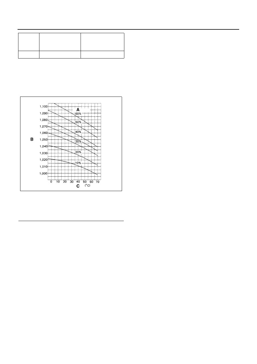
• Mixing ratio
Check the specific gravity of engine coolant in the
cooling system in temperature ranges from 0
° to
50
°C using a suction type hydrometer, then deter-
mine the mixing ratio of the coolant by referring to
the table.
50
5.0
(4.40/5.28)
5.0
(4.40/5.28)
Legend
A. Mixing ratio
B. Specific gravity
C. Coolant temperature
Mixing
ratio (%)
Specified coolant
solution:
lit. (imp. qt./U.S. qt)
Water:
lit. (imp. qt/U.S. qt)
N6A3377E