Isuzu N-Series. Service manual - part 603


  Index      Isuzu     Isuzu N-Series - service and repair manual


Search            


Content   ..  601  602  603  604   ..


Isuzu N-Series. Service manual - part 603


6A1-100 4JB1/4JB1-TC/4JG2/4JH1-TC - ENGINE

• A/C compressor pulley lock bolt loose, adjust belt

tension with adjuster’s adjust bolt.

Tighten:

• Idler lock nut to 27 N

⋅m (2.8 kg⋅m / 20 lb⋅ft)

8. Oil Pressure Switch Harness

• Connect the oil pressure switch harness connec-

tor.

9. Fuel Hose

• Connect the fuel feed hose and return hose then

tighten clip securely.

10. Glow Plug Harness

• Install the harness connector then tighten bolt se-

curely.

11. Engine Control Cable

1) Install the control wire to the engine control le-

ver.

2) Hold accelerator lever in the fully closed posi-

tion and stretch the control cable in the direc-
tion indicated by the arrow to remove any slack.

3) Tighten the accelerator cable bracket bolt.

12. Heater Hose

• Connect the heater hose then tighten clip securely.

13. Intake Air Duct

• Connect the air duct then tighten clip securely.

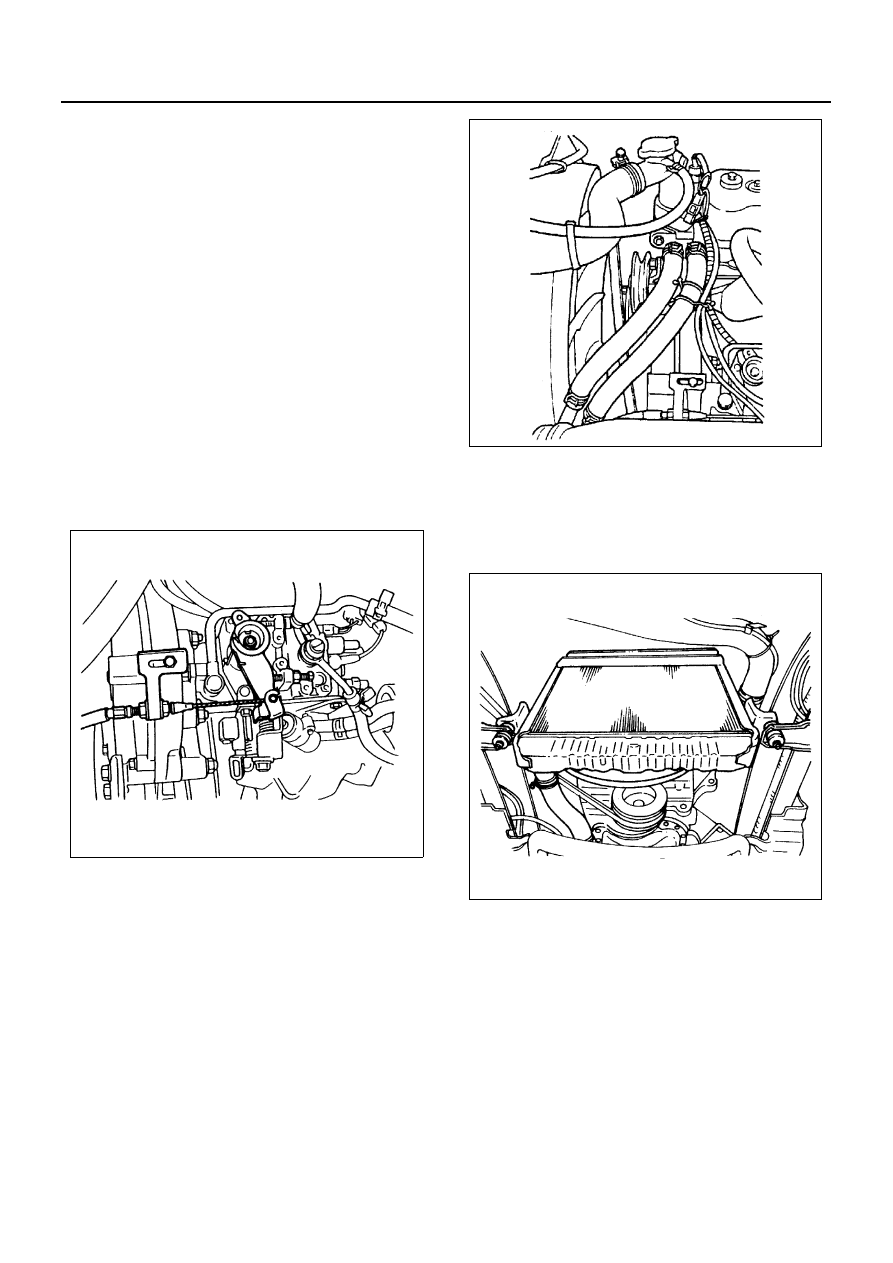
14. Radiator Assembly

1) Install the cushion rubber on both sides.
2) Install the radiator stay
3) Connect the radiator hose upper and lower.
4) Connect the reservoir tank hose.

15. Transmission and Clutch Assembly

1) Driven Plate Assembly

• Apply multi-purpose with MOS2 type grease to

the driven plate hub spline.

• Use the pilot aligner to install the driven plate

assembly.
Pilot Aligner: 5-5825-3001-0

N6A3368E

N6A3360E

N6A3359E

4JB1/4JB1-TC/4JG2/4JH1-TC - ENGINE 6A1-101

2) Pressure Plate Assembly

• Tighten pressure plate assembly fixing bolts in

numerical order.

Tighten:

• Pressure plate fixing bolt to 18 N

⋅m (1.8 kg⋅m / 13

lb

⋅ft)

• Remove the pilot aligner.

Notice:
In case a new pressure plate assembly is mounted, after
tightening a pressure plate at the specified torque, be
sure to remove the wiring for protection of a diaphragm
spring.

3) Mounting Bracket

Tighten:

• Mounting bracket nuts to 69 N

⋅m (7.0 kg⋅m / 51 lb⋅ft)

4) Transmission Assembly

• Support the transmission with mission jack.

Caution:
To prevent the falling of the transmission, tie it securely
to the jack with a chain or belt.

• Shift transmission into high gear.
• Align transmission with engine slope.
• Turn output parking brake drum to aid clutch

spring engagement.

Tighten:

• Clutch housing to flywheel hosing bolts to

M10: 46 N

⋅m (4.7 kg⋅m / 34 lb⋅ft)

M12: 91 N

⋅m (9.3 kg⋅m / 67 lb⋅ft)

• Raise engine and transmission up into rear

transmission mount.

Tighten:

• Engine rear mounting nuts to

M10: 40 N

⋅m (4.1 kg⋅m / 30 lb⋅ft)

M12: 69 N

⋅m (7.0 kg⋅m / 51 lb⋅ft)

5) Front Exhaust Pipe

N6A3339E

N6A3341E

N6A3338E

N6A3343E

6A1-102 4JB1/4JB1-TC/4JG2/4JH1-TC - ENGINE

Tighten:

• Front exhaust pipe bolts to 37 N

⋅m (3.8 kg⋅m / 27 lb⋅ft)

6) Exhaust Brake Assembly

Tighten:

• Exhaust brake bolts to 17 N

⋅m (1.8 kg⋅m / 12 lb⋅ft)

7) Clutch Slave Cylinder

Tighten:

• Slave cylinder bolts to 19 N

⋅m (1.9 kg⋅m / 14 lb⋅ft)

• Perform slave cylinder adjustment before in-

stallation of the return spring.
a. Loosen the lock nut of the push rod.
b. Turn the adjust nut until it reaches the shift

fork.

c. Back off the adjust nut 1.5 turns. (shift fork

free play Approximately 2 mm / 0.1 in).

d. Tighten the lock nut.

Tighten:

• Push rod lock nut to 16 N

⋅m (1.6 kg⋅m / 12 lb⋅ft)

8) Shift Cable and Select Cable
9) Wiring Connector

• Color of Connector

Back-up Light Switch: Brown
Neutral Switch: Gray

10) Parking Brake Cable
11) Propeller Shaft

• Line up reference mark.

Tighten:

• Propeller shaft nuts to 66 N

⋅m (6.7 kg⋅m / 48 lb⋅ft)

• Connect battery ground cable
• Pour coolant
• Start the engine and check coolant leakage

ENGINE COOLING 6B-1

ENGINE 4J SERIES

SECTION 6B

ENGINE COOLING

Contents

GENERAL DESCRIPTION ................................... 6B-2

Component ........................................................ 6B-2

WATER PUMP...................................................... 6B-7

Component ........................................................ 6B-7
Removal ............................................................ 6B-7
Inspection .......................................................... 6B-8
Installation ......................................................... 6B-9

THERMOSTAT ................................................... 6B-11

Component ...................................................... 6B-11
Removal .......................................................... 6B-11
Inspection ........................................................ 6B-11
Installation ....................................................... 6B-12

RADIATOR.......................................................... 6B-13

Component ...................................................... 6B-13
Removal .......................................................... 6B-13
Inspection ........................................................ 6B-13
Installation ....................................................... 6B-14

DRIVE BELT ADJUSTMENT .............................. 6B-15

Component ...................................................... 6B-15
Inspection ........................................................ 6B-16
Tension Adjustment......................................... 6B-16


Content   ..  601  602  603  604   ..