Isuzu N-Series. Service manual - part 587


  Index      Isuzu     Isuzu N-Series - service and repair manual


Search            


Content   ..  585  586  587  588   ..


Isuzu N-Series. Service manual - part 587


6A1-36 4JB1/4JB1-TC/4JG2/4JH1-TC - ENGINE

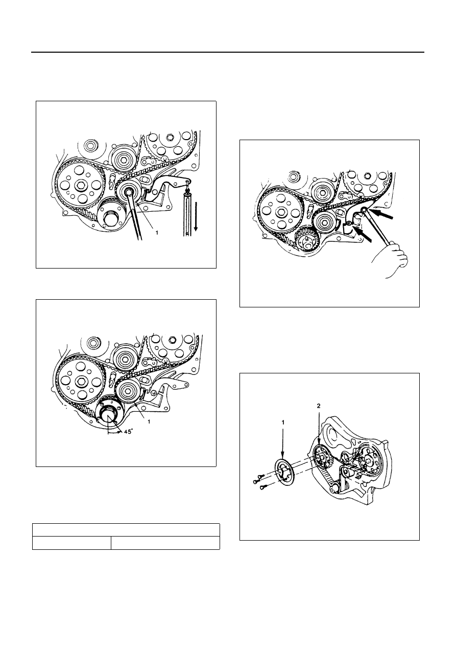
• Hung a spring balance from the end hole of tension

adjust lever, and with the balance pulled down with
9 kg., loosen once the tensioner (1) mounting bolt
and there retighten it.

• Turn the crankshaft by 45

° counterclockwise to

shift belt slackness on to the tensioner (1).

• Again hang the spring balance from the end hole of

tension adjust lever and pull it down with the spec-
ified force. Under this condition, loosen tensioner
mounting bolt to absorb belt slackness and retight-
en is to specified torque.

Tighten:

• Bolt to 76 N

⋅m (7.8 kg⋅m / 56 lb⋅ft)

• Fix the tension adjust lever.

Caution:

• In case where the timing belt has been replaced

with the actuation of warning light, put off the light
with change over switch on the reverse side of
meter.

• Refer to Chassis Electrical in Section 8.

• Tighten the tension adjusting lever nut and bolt.

2. Flange; Camshaft Pulley

• Install the timing pulley flange (1) to the camshaft

timing pulley (2).

Tighten:

• Flange bolts to 19 N

⋅m (1.9 kg⋅m / 14 lb⋅ft)

3. Timing Pulley Lower Cover

• Install timing pulley lower cover and tighten bolt to

the specified torque.

Tighten:

• Cover bolts to 8 N

⋅m (0.8 kg⋅m / 69 lb⋅in)

Belt

N

⋅(kg/lb)

Tension

98 — 118 (10 — 12/22 — 26)

N6A3152E

N6A3153E

N6A3155E

N6A3712E

4JB1/4JB1-TC/4JG2/4JH1-TC - ENGINE 6A1-37

4. Timing Pulley Upper Cover

• Install timing pulley upper cover and tighten bolt to

the specified torque.

Tighten:

• Cover bolts to 8 N

⋅m (0.8 kg⋅m / 69 lb⋅in)

5. Crankshaft Damper Pulley

• Install crankshaft damper pulley and tighten bolt to

the specified torque.

Tighten:

• 19 N

⋅m (1.9 kg⋅m / 14 lb⋅ft)

6. Power Steering Pump Bracket Assembly (P/S

Model)

• Install the pipe bracket & clip and tighten bolts to

the specified torque.

Tighten:

• Pipe bracket bolts to 19 N

⋅m (1.9 kg⋅m / 14 lb⋅ft)

• Pipe clip bolts to 10 N

⋅m (1.0 kg⋅m / 87 lb⋅in)

• Install the P/S pump & bracket assembly.

Tighten:

• M10 bolts to 40 N

⋅m (4.1 kg⋅m / 30 lb⋅ft)

• M8 bolts to 19 N

⋅m (1.9 kg⋅m / 14 lb⋅ft)

• Lock nut to 27 N

⋅m (2.8 kg⋅m / 20 lb⋅ft)

Legend

1. Lower cover
2. Upper cover

N6A3713E

N6A3158E

Legend

1. Pipe bracket
2. Clip
3. Lock nut

N6A3159E

N6A3700E

6A1-38 4JB1/4JB1-TC/4JG2/4JH1-TC - ENGINE

7. AC Generator Drive Belt

• Install AC Generator drive belt and adjust belt ten-

sion.

• Depress the drive belt mid-portion with a 98 N (10

kg / 22 lb) force.

• Install fixing bolt and tighten bolts to the specified

torque.

Tighten:

• Generator fixing bolts to 40 N

⋅m (4.1 kg⋅m / 30 lb⋅ft)

• Adjust plate fixing bolts to 19 N

⋅m (1.9 kg⋅m / 14 lb⋅ft)

8. A/C Compressor Drive Belt (A/C type)

• Install A/C compressor drive belt and adjust belt

tension.

• Depress the drive belt mid-portion with a 98 N (10

kg / 22 lb) force.

• Tighten the idler lock nut to the specified torque.

Tighten:

• Idler lock nut to 27 N

⋅m (2.8 kg⋅m / 20 lb⋅ft)

9. Power Steering Pump Drive Belt (P/S pump model)

• Install PS pump drive belt and adjust belt tension.
• Depress the drive belt mid-portion with a 98 N (10

kg / 22 lb) force.

• Tighten the idler lock nut to the specified torque.

Tighten:

• Idler lock nut to 27 N

⋅m (2.8 kg⋅m / 20 lb⋅ft)

10. Fan Shroud

• Install the fan shroud and reservoir tank hose.

11. Cooling Fan Assembly

• Mount fan pulley, distance piece, and cooling fan

asm (in this order) on the water pump, and tighten
to the specified torque.

Tighten:

• Nut to 8 N

⋅m (0.8 kg⋅m / 69 lb⋅in)

• Connect battery ground cable.
• Pour coolant.
• Start the engine and check coolant leakage.

Drive Belt Deflection

mm (in)

8 (0.31) — 12(0.47)

Drive Belt Deflection

mm (in)

8 (0.31) — 12(0.47)

Legend

1. A/C compressor drive belt
2. P/S pump drive belt
3. AC generator fan pulley

N6A3297E

Drive Belt Deflection

mm (in)

8 (0.31) — 12(0.47)

N6A3223E

4JB1/4JB1-TC/4JG2/4JH1-TC - ENGINE 6A1-39

CYLINDER HEAD ASSEMBLY AND GASKET

Component

Removal

Preparation

• Disconnect battery ground cable.

• Drain coolant from the radiator and engine.

1. Radiator Hose Upper

• Disconnect upper radiator hose from engine side.

Legend

1. Radiator hose upper

11. Oil cooler water pipe

2. Heater hose

12. A/C Compressor assembly

3. A/C Compressor drive belt

13. Vacuum actuator hose

4. Engine harness

14. Front exhaust pipe

5. Air intake duct

15. By-pass hose

6. Injection pipe

16. Cylinder head cover

7. Leak off pipe

17. Rocker arm shaft

8. PCV hose

18. Push rod

9. Glow plug harness

19. Cylinder head assembly

10. Oil level gauge guide tube

20. Cylinder head gasket

N6A3285E


Content   ..  585  586  587  588   ..