Isuzu N-Series. Service manual - part 575


  Index      Isuzu     Isuzu N-Series - service and repair manual


Search            


Content   ..  573  574  575  576   ..


Isuzu N-Series. Service manual - part 575


GENERAL ENGINE MECHANICAL 6A-57
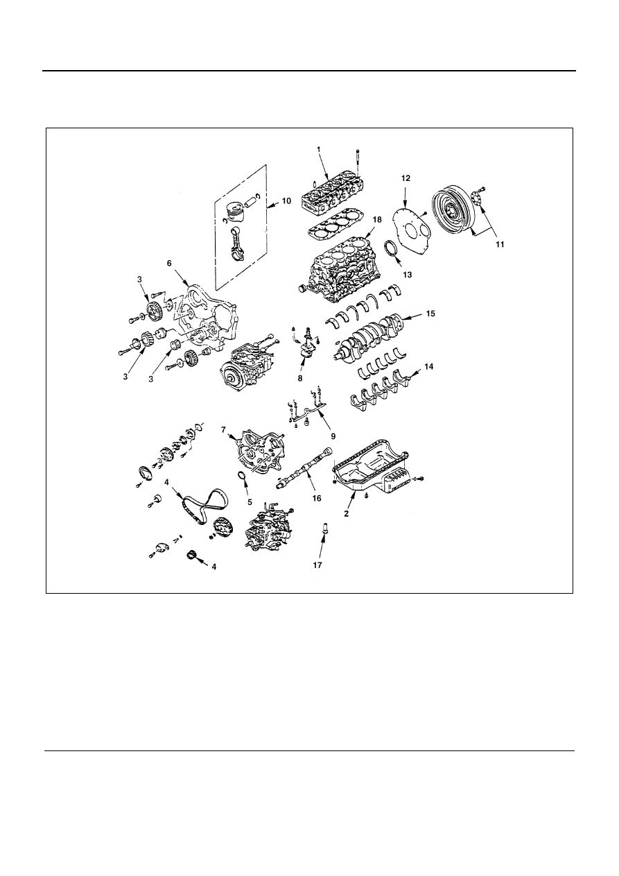
CYLINDER BLOCK

Component

Disassembly

1. Cylinder Head Assembly and Gasket
2. Oil Pan Assembly
3. Timing Gear

4. Timing Belt and Pulley
5. Front Oil Seal (Belt Drive Model)
6. Timing Gear Housing
7. Timing Pulley Housing

Legend

1. Cylinder head assembly and gasket

10. Piston and connecting rod

2. Oil pan assembly

11. Flywheel

3. Timing gear

12. Cylinder block rear plate

4. Timing belt and pulley

13. Crankshaft rear oil seal

5. Front oil seal (Belt Drive Model)

14. Main bearing cap

6. Timing gear housing

15. Crankshaft

7. Timing pulley housing

16. Camshaft

8. Oil pump assembly

17. Tappet

9. Piston cooling oil pipe

18. Cylinder block

N6A3192E

6A-58 GENERAL ENGINE MECHANICAL

8. Oil Pump Assembly
9. Piston Cooling Oil Pipe

10. Piston and Connecting Rod
11. Flywheel
12. Cylinder Block Rear Plate
13. Crankshaft Rear Oil Seal
14. Main Bearing Cap
15. Crankshaft
16. Camshaft
17. Tappet
18. Cylinder Block

Inspection and Repair

Make the necessary adjustments, repairs, and part re-
placements if excessive wear or damage is discovered
during inspection.

1. Remove the gasket and any other material adher-

ing the upper surface of the cylinder block.
Be very careful not to allow any material to acci-
dental drop into the cylinder block.
Be very careful not to scratch the cylinder block.

2. Carefully remove the oil pump, Rear Seal retainer

and oil pan installation surface seal.

3. Wipe the cylinder block clean.

Cylinder Liner Projection Inspection

1. Hold a straight edge (1) along the top edge of the

cylinder liner to be measured.

2. Use a feeler gauge (2) to measure each cylinder

line projection.
The difference in the cylinder liner projection height
between any two adjacent cylinders must not ex-
ceed 0.03 mm (0.0012 in).

Flatness

1. Remove the cylinder body dowel.
2. Set the cylinder liner remover to the cylinder liner.
3. Check that the remover shaft ankle is firmly grip-

ping the cylinder liner bottom edge.

4. Slowly turn the remover shaft handle counterclock-

wise to pull the cylinder liner free.
Cylinder Liner Remover Ankle: 
5-8840-2304-0 (4JG2/4JH1-TC)
5-8840-2039-0 (4JB1/4JB1-TC)

Notice:
Take care not to damage the cylinder body upper during
the cylinder liner removal procedure.

5. Use a straight edge and a feeler gauge to measure

the four sides and the two diagonals of the cylinder
body upper face.
If the measured values exceeds the limit, the cylin-
der body must be replaced.

Standard

mm (in)

0.0 — 0.1 (0.0000 — 0.0039)

N6A3193E

N6A3194E

N6A3195E

GENERAL ENGINE MECHANICAL 6A-59

Cylinder Liner Bore Measurement

Use a cylinder indicator to measure the cylinder liner
bore at measuring point (1) in the thrust (2) — (2) and
axial (3) direction of the crankshaft.
Measuring Point (1) 20mm (0.79 in)
If the measured value exceeds the specified limit, the
cylinder liner must be replaced.

Notice:
The inside of the dry type cylinder liner is chrome plated.
It cannot be rebored or honed.
If the inside of the cylinder liner is scored or scorched,
the cylinder liner must be replaced.

Cylinder Liner Grade Selection

Measure the cylinder body inside diameter and select
the appropriate cylinder liner grade.

If the cylinder liner fitting interference (1) is too small, en-
gine cooling efficiency will be adversely effected.
If the cylinder liner fitting interference is too large, it will
be difficult to insert the cylinder liner into the cylinder
body.

Cylinder Body Bore Measurement

1. Take measurements at measuring point (A) across

positions (1) — (1), (2) — (2), (3) — (3), and (4) —
(4).

Measuring Point (A) 98mm (3.86 in).

Standard Lifting Interference

mm (in)

0.01 — 0.019 (0.0004 — 0.0007)

N6A3196E

N6A3197E

N6A3198E

N6A3199E

6A-60 GENERAL ENGINE MECHANICAL

2. Calculate the average value of the four measure-

ments to determine the correct cylinder grade.

3. Consult the following table with the resultant diam-

eter for the correct liner application.

Selection method of cylinder liner and piston grade
for service parts.
The production line stamped cylinder liner grade on the
top of cylinder body, the cylinder liner outside diameter
grade 1, 2, 3, 4.
If you find cylinder liner outside diameter grade 1 and
piston outside diameter B on the cylinder body or result
of measurement for each parts, you will select service
parts grade for cylinder liner 1, AX grade and for piston
AX grade.
The stamping grade code on the service parts are;
For cylinder liner grade stamped on the outside of cylin-
der liner.
For piston grade stamped on the head of piston.

Notice:
It is most important that the correct piston grade be
used. Failure to select the correct piston grade will result
in engine failure. Always measure the cylinder bore and
select the correct piston grade.

Cylinder liner kit clearances are preset. However, the
cylinder liner installation procedure may result in slight
decreases in cylinder liner clearances. Always measure
the cylinder liner clearance after installation to be sure
that it is correct.

N6A3200E

4JB1 / 4JB1-TC

mm (in)

Liner 

outside 

Grade

Cylinder bore diameter 

average

Liner outside diameter

Liner bore 

Grade

Service liner bore measurement

1

95.001 — 95.010 

(3.7402 — 3.7406)

95.011 — 95.020 

(3.7406 — 3.7409)

AX

93.035 (3.6628) — 93.050 (3.6634)

CX

93.051 (3.6634) — 93.066 (3.6640)

2

95.011 — 95.020 

(3.7406 — 3.7409)

95.021 — 95.030 

(3.7410 — 3.7413) 

AX

93.035 (3.6628) — 93.050 (3.6634)

CX

93.051 (3.6634) — 93.066 (3.6640)

3

95.021 — 95.030 

(3.7410 — 3.7413)

95.031 — 95.040 

(3.7414 — 3.7417)

AX

93.035 (3.6628) — 93.050 (3.6634)

CX

93.051 (3.6634) — 93.066 (3.6640)

4

95.031 — 95.040 

(3.7414 — 3.7417)

95.041 — 95.050 

(3.7418 — 3.7421)

AX

93.035 (3.6628) — 93.050 (3.6634)

CX

93.051 (3.6634) — 93.066 (3.6640)

4JG2 / 4JH1-TC

mm (in)

Liner 

outside 

Grade

Cylinder bore diameter 

average

Liner outside diameter

Liner bore 

Grade

Service liner bore measurement

1

97.001 — 97.010 

(3.8189 — 3.8193)

97.011 — 97.020 

(3.8193 — 3.8197)

AX

95.435 (3.7573) — 95.450 (3.7579)

CX

95.451 (3.7579) — 95.466 (3.7585)

2

97.011 — 97.020 

(3.8193 — 3.8197)

97.021 — 97.030 

(3.8197 — 3.8201)

AX

95.435 (3.7573) — 95.450 (3.7579)

CX

95.451 (3.7579) — 95.466 (3.7585)

3

97.021 — 97.030 

(3.8197 — 3.8201)

97.031 — 97.040 

(3.8201 — 3.8205)

AX

95.435 (3.7573) — 95.450 (3.7579)

CX

95.451 (3.7579) — 95.466 (3.7585)

4

97.031 — 97.040 

(3.8201 — 3.8205)

97.041 — 97.050 

(3.8205 — 3.8209)

AX

95.435 (3.7573) — 95.450 (3.7579)

CX

95.451 (3.7579) — 95.466 (3.7585)


Content   ..  573  574  575  576   ..