Isuzu N-Series. Service manual - part 574


  Index      Isuzu     Isuzu N-Series - service and repair manual


Search            


Content   ..  572  573  574  575   ..


Isuzu N-Series. Service manual - part 574


GENERAL ENGINE MECHANICAL 6A-53

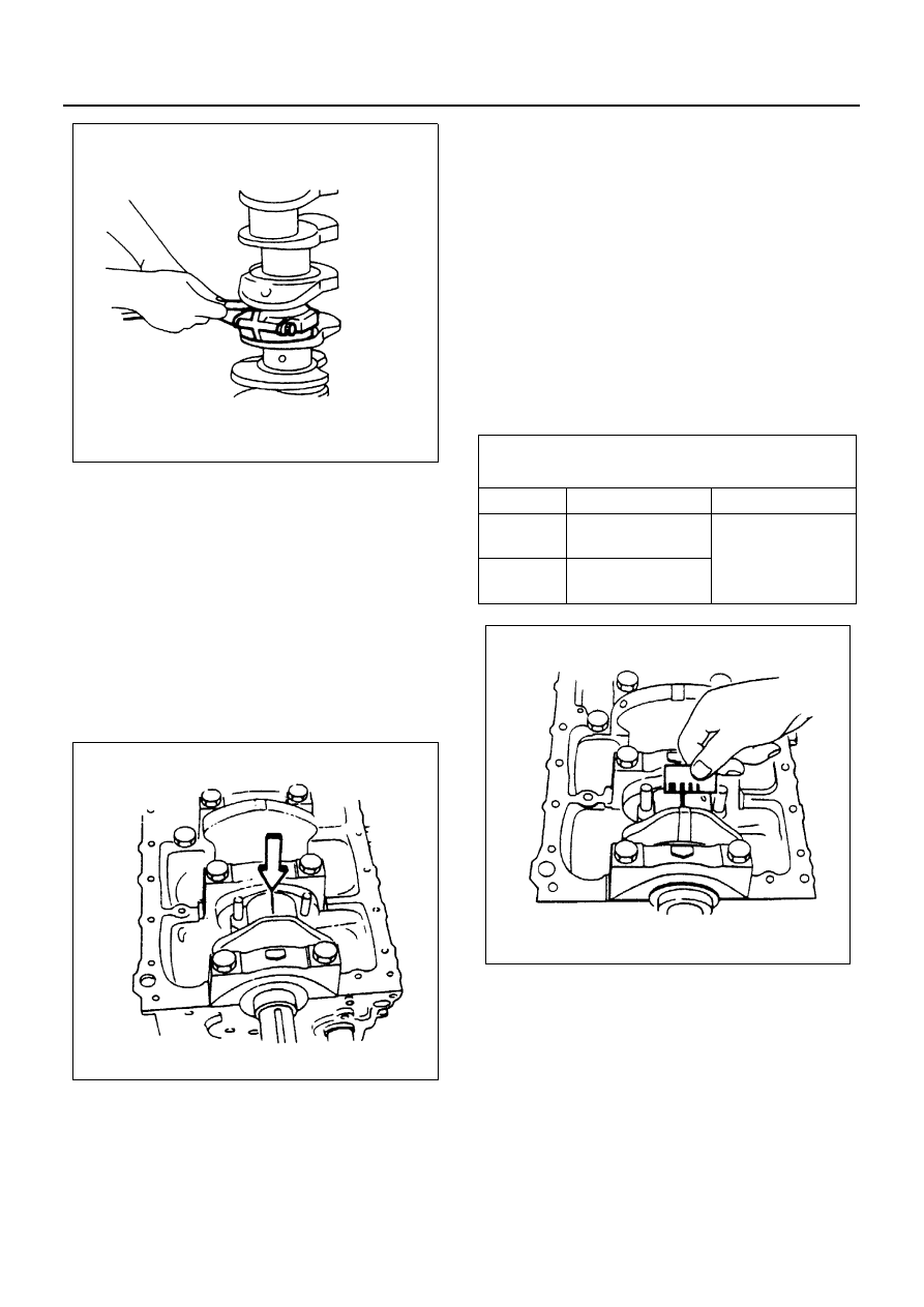
3. Measure the oil clearance between the connecting

rod and the crankshaft by:
1) Remove the connecting rod cap nuts and the

rod caps.
Arrange the removed rod caps in the cylinder
number order.

2) Clean the rod bearings and the crankshaft pins.
3) Carefully check the rod bearings.

If even one bearing is found to be damaged or
badly worn, the entire bearing assembly must
be replaced as a set. Reinstall the bearings in
their original positions.
Apply plastigage to the crank pin.

4) Put the plastigage, and reinstall the rod caps to

their original positions.

5) Tighten the cap nuts in 2 steps, using angular

tightening method as shown in the following
specifications. (4JG2, 4JH1-TC, 4JB1-TC)

Tighten:

• 4JH1-TC, 4JB1-TC to

1st Step: 29 N

⋅m (3 kg⋅m/22 lb⋅ft)

2nd Step: 45

° — 60°

• 4JB1 to 83 N

⋅m (8.5 kg⋅m/61 lb⋅ft)

Notice:
Do not allow the crankshaft to rotate.

6) Remove the rod caps.
7) Measure the width of the plastigage and deter-

mine the oil clearance. If the oil clearance ex-
ceeds the limit, replace the rod bearings as a
set.

8) Remove the plastigage from the bearings and

the crankshaft pins.

Reassembly

1. Connecting Rod
2. Piston
3. Piston Pin

Apply a cost of engine oil to the piston pin and the
piston pin hole.

N6A3184E

N6A3185E

Crankshaft Journal and Bearing Clearance

mm (in)

Standard

Limit

4JB1 / 

4JB1-TC

0.029 — 0.066 

(0.0011 — 0.0026)

0.100 (0.0039)

4JG2

4JH1-TC

0.029 — 0.083 

(0.0011 — 0.0033

N6A3186E

6A-54 GENERAL ENGINE MECHANICAL

4. Piston Pin Snap Ring

Apply a thin coat of engine oil to the piston pin.
Try to insert the piston pin into the piston pin hole
with normal finger pressure.
Weigh each piston and connecting rod assembly.
Select piston and connecting rod combinations so
that the weight variation of the different assemblies
a held within the specified limits.

Notice:
When changing piston/connecting rod combinations, do
not change the piston/piston pin combination

• Attach the piston to the connecting rod with the

piston front mark and the connecting rod ISU-
ZU mark on the same side.

5. Piston Ring

• Install the piston rings with the piston ring ex-

pander.
The compression ring must be set with the N
mark facing up.

• Discrimination mark is painted as shown in the

illustration.

• Install piston rings in the following sequence.

1) Oil ring

4JB1, 4JH1-TC

2) 2nd compression ring
3) 1st compression ring

• The compression ring must be set with the

1N or 2N mark (4JG2) facing up.

• 1st compression ring: 1N (4JG2), N (4JB1),

R (4JH1-TC)

g (oz)

Variance in weight after 

assembly

Less than 3 (0.1058)

Legend

1. Front mark
2. ISUZU mark

N6A3187E

Legend

1. N mark (Top ring) (2nd ring) (4JB1)
2. 1N mark (Top ring) 2N mark (2nd ring) (4JG2)
3. R mark (Top ring) (2nd ring) (4JH-TC)

Legend

1. Expander ring
2. Upper side rail
3. Lower side rail

N6A3178E

N6A3188E

GENERAL ENGINE MECHANICAL 6A-55

• 2nd compression ring: 2N (4JG2), N (4JB1),

R (4JH1-TC)

• After installation, apply engine oil to the en-

tire circumference of the piston rings.
Check to see that all the rings rotate smooth-
ly.

• Insert the bearings into the connecting rods

and caps.
Apply new engine oil to the bearing faces.
Cap side bearings have no oil hole.
Connecting rod side bearings oil hole should
be aligned with oil hole on the connecting
rod.

4JG2

6. Piston and Connecting Rod

• Apply engine oil to the cylinder bores, the con-

necting rod bearings and the crankshaft pins.

• Check to see that the piston ring end gaps are

correctly positioned.

• Insert the piston/connecting rod assemblies

into each cylinder with the piston ring compres-
sor.

• The front marks must be facing the front of the

engine.

7. Connecting Rod Bearing Cap

• Tighten the cap nuts in 2 steps, using angular

tightening method as shown in the following
specifications.

Tighten:
4JH1-TC, 4JB1-TC to

• 1st Step: 29 N

⋅m (3.0 kg⋅m/22 lb⋅ft)

• 2nd Step: 45

° — 60°

4JB1 to 83 N

⋅m (8.5 kg⋅m/61 lb⋅ft)

After tightening the cap nuts, check to see that the
crankshaft rotates smoothly.

8. Piston Cooling Oil Pipe

• Install the piston cooling oil pipe to the cylinder

body.

• Tighten the oil pipe bolts and relief valve to the

specified torque.

Tighten:
Oil Pipe Bolt to

• M8 

× 1.25: 19 N⋅m (1.9 kg⋅m/14 lb⋅ft)

• M6 

× 1.00: 8 N⋅m (0.8 kg⋅m/69 lb⋅in)

Oil Pressure Regulating Valve to

• M16 

× 1.5: 29 N⋅m (3.0 kg⋅m/22 lb⋅ft)

Legend

1. Oil ring
2. Compression ring No. 2
3. Compression ring No. 1

N6A3189E

Legend

1. Expander ring
2. Expander ring
3. Upper side rail
4. Lower side rail

N6A3190E

6A-56 GENERAL ENGINE MECHANICAL

Notice:
Check that there is no interference between the piston
and the oiling jet pipe by slowly rotating the crankshaft.

9. Oil Pump Assembly

10. Oil Pan Assembly

Above works refer to “OIL PUMP” Section in this
manual.

11. Cylinder Head Assembly

• Piston Head Projection Measurement Point
• Cylinder Head Assembly
• Push Rod
• Rocker Arm Shaft Assembly

Valve clearance adjustment.
Above works refer to “CYLINDER BLOCK” Section
in this manual.

N6A3191E


Content   ..  572  573  574  575   ..