Isuzu N-Series. Service manual - part 570


  Index      Isuzu     Isuzu N-Series - service and repair manual


Search            


Content   ..  568  569  570  571   ..


Isuzu N-Series. Service manual - part 570


GENERAL ENGINE MECHANICAL 6A-37

4. Cylinder Block Rear Plate

Align the rear plate with the cylinder body knock
pins.
Tighten the rear plate to the specified torque

Tighten:
82 N

⋅m (8.4 kg⋅m/61 lb⋅ft)
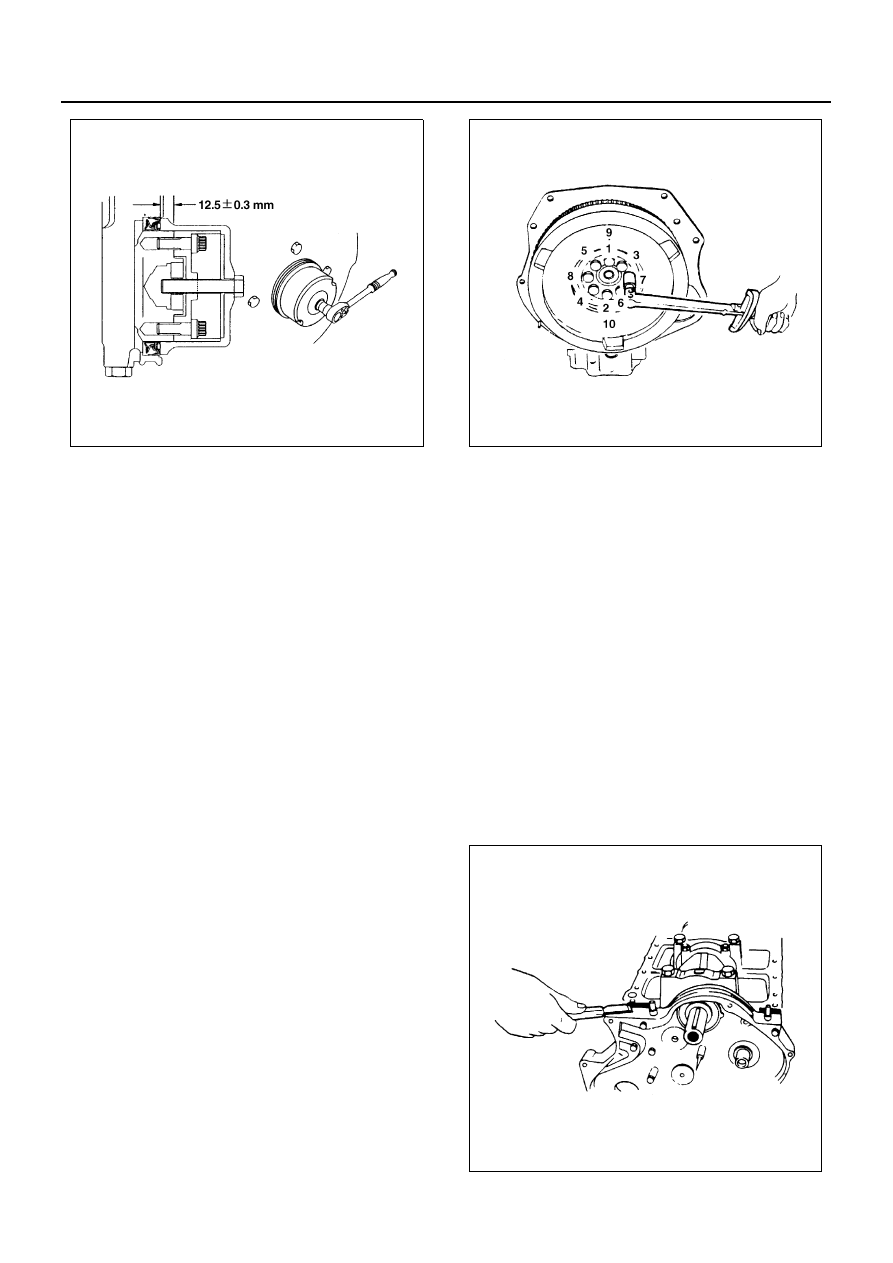
5. Flywheel

1) Thoroughly clean the remove the oil from the

threads of crankshaft.

2) Mount the flywheel on the crankshaft and then

install the washer.

3) Apply a coat of engine oil to the threads of the

flywheel bolts.

4) Align the flywheel with the crankshaft dowel

pin.

5) Tighten the flywheel bolts to the specified

torque in two steps using the Angular Tighten-
ing Method.
Follow the numerical order shown in the illus-
tration.

Tighten:

• Flywheel Bolt to

1st Step: 59 N

⋅m (6.0 kg⋅m/43 lb⋅ft)

2nd Step: 60

° — 90°

6. Piston and Connecting Rod
7. Piston Cooling Oil Pipe
8. Oil Pump Assembly

Above works refer to “PISTON AND CONNECT-
ING ROD” 
Section in this manual.

9. Timing Pulley Housing

1) Install the timing pulley housing to the cylinder

body.

Notice:
Take care not to twist the front oil seal.

2) Tighten the timing pulley housing bolt together

with the timing pulley housing gasket to the
specified torque.

Tighten:
19 N

⋅m (1.9 kg⋅m/14 lb⋅ft)

3) Cut away the gasket protruding above the fit-

ting surfaces (as shown in the illustration).

10. Timing Gear Housing

N6A3145E

N6A3112E

N6A3146E

6A-38 GENERAL ENGINE MECHANICAL

1) Install the timing gear housing to the cylinder

body.

2) Tighten the timing gear housing bolt together

with the timing gear housing gasket to the spec-
ified torque.

Tighten:
19 N

⋅m (1.9 kg⋅m/14 lb⋅ft)

3) Cut away the gasket protruding above the fit-

ting surface (as shown in the illustration).

11. Front Oil Seal (Gear Drive Model)

• Install oil seal using special tool.

Installer: 5-8840-2061-0

12. Front Oil Seal (Belt Drive model)

• Install oil seal using special tool.

Installer: 5-8840-2361-0

Notice:
Wipe off rust and scraps clean from the press-in portion
of the oil seal.
Take note of the press-in direction of the oil seal.

1) With the oil seal attached to the sleeve, put it in

the front end of the crankshaft.

2) With the edge of the oil seal attached securely

to the crankshaft, tighten it with the center bolt
until the sleeve hits securely against the refer-
ence plane at the front end of the crankshaft.

3) Remove the sleeve.
4) After pressing in the oil seal, check the mea-

surement of the oil seal.

13. Camshaft Timing Pulley (Belt Drive model)

1) Apply engine oil to the oil seal lip portion of the

oil seal retainer.

2) Apply the recommended liquid gasket or its

equivalent to the retainer.

3) Install the oil seal retainer to the cylinder body.
4) Tighten the retainer bolts to the specified

torque.

Tighten:
Oil Seal Retainer Bolt to 19 N

⋅m (1.9 kg⋅m/14 lb⋅ft)

5) Align the camshaft timing pulley center with the

camshaft key.

6) Tighten the timing pulley bolts to the specified

torque.

Tighten:
Timing Pulley Bolt to 8 N

⋅m (0.8 kg⋅m/69 lb⋅ft)

Legend

1. Oil seal
2. Timing pulley housing

Standard

mm (in)

0.6 — 1.2 (0.024 — 0.047)

N6A3147E

Legend

1. Retainer

N6A3148E

N6A3107E

GENERAL ENGINE MECHANICAL 6A-39

7) Prevent the camshaft from turning when tight-

ening the timing center bolt.

8) Tighten the timing pulley center bolt to the

specified torque.

Tighten:
Center Bolt to 64 N

⋅m (6.5 kg⋅m/47 lb⋅ft)

9) Install the crank pulley.
10) Install the idle pulley and idler pulley.

Tighten:
76 N

⋅m (7.8 kg⋅m/56 lb⋅ft)

11) Install the injection pump assembly and install

timing pulley.

12) Align the timing pulley with the pump shaft key.
13) Install the stopper bolt to the timing pulley.

This will prevent the timing pulley from moving.

14) Tighten the timing pulley nut to the specified

torque.

Tighten:
Injection Pump Timing Pulley Nut to 64 N

⋅m (6.5 kg⋅m/

47 lb

⋅ft)

15) Remove the stopper bolt from the injection tim-

ing.

14. Timing Belt (Belt Drive model)

Notice:

• When the timing belt is removed, be sure to re-

place it with a new one.

• The tension of the timing belt may be affected by

the changes in temperature. Be sure to install it
while the engine cold.

• When the timing belt is bent forcibly, the cord may

got snapped, thus resulting in the reduced
strength. Do not bend it unnecessarily.

1) Check that the stopper bolts are properly in-

stalled to the camshaft timing pulley and the in-
jection pump timing pulley.

2) Check that the timing pulley housing mark and

the crankshaft timing pulley mark are aligned.
The No. 1 cylinder should be at TDC on the
compression stroke.
Rotate the crankshaft damper pulley clockwise
to align the marks.

Legend

1. Timing pulley center
2. Timing pulley

Legend

1. Lock bolt

N6A3108E

N6A3110E

N6A3149E

6A-40 GENERAL ENGINE MECHANICAL

3) Install the timing belt to the crankshaft timing

pulley (1), the camshaft timing pulley (2), the
tensioner idler (3), and the injection timing pul-
ley (4).
Follow the numerical order.

4) Install the timing belt tensioner (5) to the timing

pulley housing.

5) Temporarily tighten the tensioner bolt.

The tensioner should move freely.

Notice:
The timing belt is easily damaged. Be careful.

Notice:
After completion of the installation of the timing belt,
check to see if the alignment mark of the crankshaft tim-
ing pulley is in line with the alignment mark provided on
the housing.

• When the alignment marks are not in line with

each other, set them together and reinstall the
timing belt.

6) Set the tensioner adjusting lever to the timing

pulley housing.

7) Remove the stopper bolts from the camshaft

timing pulley and the injection pump timing pul-
ley.

8) Attach the spring balancer.
9) Adjust the timing belt tension by pulling straight

down on the spring balancer with the specified
force.

Legend

1. Lock bolt
2. Setting mark

N6A3150E

N6A3151E

Legend

1. Lock bolt
2. Setting mark

Tension Adjusting Lever Force

N (kg/lb)

98 — 118 (10 — 12/22 — 26)

N6A3150E


Content   ..  568  569  570  571   ..