Isuzu N-Series. Service manual - part 533
6C-40 Fuel System
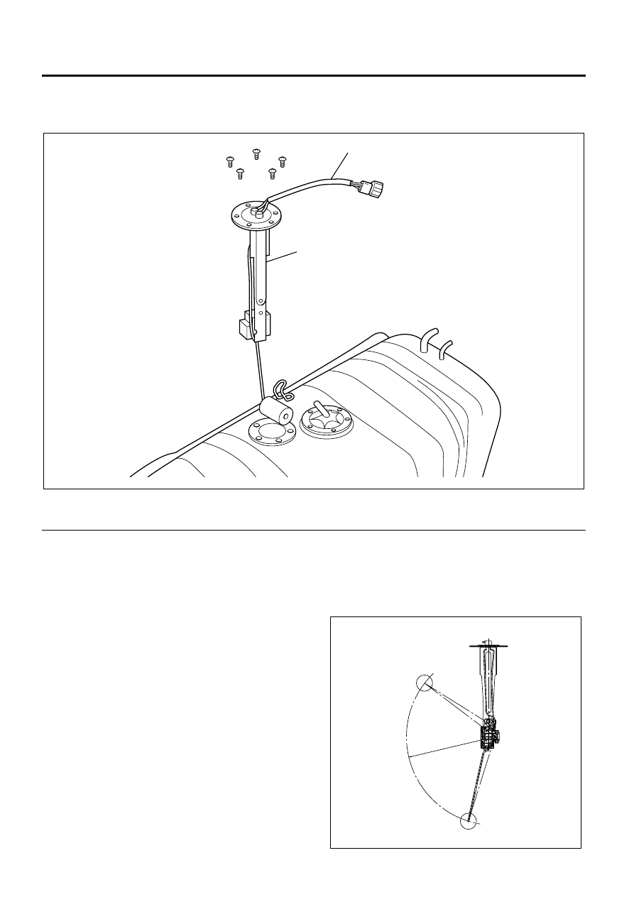
Fuel Gauge Unit
Components
Legend
1. Fuel Gauge Unit Connector
2. Fuel Gauge Unit
Removal
1. Remove the wiring connector from the fuel gauge
unit.
2. Remove the installed screw and remove the fuel
gauge unit.
Caution:
When removing/installing the fuel gauge unit, take care
not to interfere with adjacent parts and not to let the
arm etc. deformed. Also, after removing the fuel gauge
unit, cover the tank with a cloth to prevent the entry of
dust.
Inspection
The fuel tank unit changes the internal resistance
according to the float position (fluid level) to operate the
indicator of the fuel meter.
1
2
N6A6391E
F
E
N6A6392E