Isuzu N-Series. Service manual - part 522


  Index      Isuzu     Isuzu N-Series - service and repair manual


Search            


Content   ..  520  521  522  523   ..


Isuzu N-Series. Service manual - part 522


Cooling System   6B-19

Radiator core

1. If the radiator fin is deformed, the radiation effect

deteriorates causing overheating. Therefore,
modify the fin. Make sure that the root base of the
fin is not damaged during modification.

• Eliminate dust or other foreign matter.

Washing the radiator

1. Wash the internal parts of the radiator and cooling

water passage using water and detergent.
Eliminate scale and rust completely.

Installation

1. Ensure that no damage occurs to the radiator core

because of the fan blade. Mount the brackets on
the left and right sides of the radiator on the frame
according to the figure.

Tighten:

Bolts to 55 N

⋅m (5.6 kg⋅m / 41 lb⋅ft)
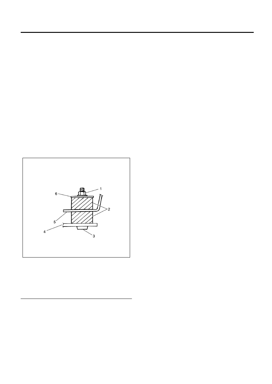
Legend

1. Flange Nut
2. Rubber
3. Stud Bolt
4. Frame
5. Bracket on The Radiator Side
6. Washer


2. Mount the reserve tank hose of the coolant on the

radiator.

3. Mount the radiator lower hose.
4. Mount the radiator upper hose.

• Fill the cooling water.

5. Install the 2 transmission oil pipes on the

underside of the radiator.

6. Install the intake pipe from the turbocharger and

inter-cooler (left side).

7. Install the intake pipe from the intake manifold and

inter-cooler (right side).

Reference
Cooling water injection procedure (in case of changing
the cooling water completely)

• Confirm that the engine has cooled.
• Open the radiator cap and the reserve tank cap.
• Pour the cooling water up to the filler neck.
• Pour the cooling water up to the “MAX” line in the

reserve tank.

• Close the radiator cap and the reserve tank cap

and start the engine. Stop the engine after running
for about 2 to 3 minutes at the idling rpm. Open the
radiator cap again and replenish if the water level
is low.

WARNING:
DO NOT LOOSEN OR REMOVE THE RADIATOR
CAP WHEN THE TEMPERATURE OF THE COOLING
WATER IS HIGH. STEAM OR BOILING WATER WILL
GUSH OUT AND YOU MAY BE BURNT. TO OPEN
THE RADIATOR CAP, COVER THE CAP WITH A
THICK CLOTH WHEN THE COOLING WATER IS
COOL, RELEASE THE PRESSURE BY SLOWLY
TURNING THE CAP, AND THEN REMOVE THE CAP.

• After tightening the radiator cap, warm up the

engine by running it at about 2000 rpm. Also,
adjust the temperature of the heater to maximum
temperature and circulate the cooling water even
in the heater water conduit system.

• When the pointer of the thermometer crosses the

median and the thermostat has activated, run at
idling rpm for another 5 minutes, then stop the
engine and leave it as-is.

• After the engine has cooled down sufficiently,

check the water level in the filler neck part and
replenish if necessary. If the level is extremely low,
check for leaks in the cooling water conduit system
and reserve tank hose.

N6A6247E

6B-20   Cooling System

• Pour the cooling water up to the “MAX” line in the

reserve tank again.

Legend

1. Reserve Tank
2. MAX Line (Upper Limit)
3. MIN Line (Lower Limit)


Torque Specifications

N6A6330E

N6A6447E

Cooling System   6B-21

Drive Belt

Components

Legend

1. Crank Pulley
2. Generator Drive Belt
3. Bolt
4. Generator
5. Adjusting Bolt
6. A/C Compressor
7. Lock Nut

8. Adjusting Plate
9. A/C Compressor Drive Belt

10. Water Pump Pulley

11. Lock Nut

12. Tension Pulley
13. Adjusting Bolt


Inspection

Check for the presence of wear or damage in the drive
belt and renew the parts if necessary.
Check the tension of the belt and adjust if necessary.

Deflection Standard
Apply a pressure of 98 N (22 lb) at the center of the
long span of each belt and check the deflection of the
belt.

N6A6353E

Deflection of A/C compressor drive belt

When the belt is new
16 to 20 mm (0.630 to 0.787 in)
When the belt is reused
18 to 22 mm (0.709 to 0.866 in)

Deflection of generator drive belt

When the belt is new
8 to 12 mm (0.315 to 0.472 in)
When the belt is reused
10 to 14 mm (0.394 to 0.551 in)

6B-22   Cooling System

Legend

1. A/C Compressor Drive Belt
2. Generator Drive Belt


Adjustment

Adjust simultaneously the generator drive belt and A/C
compressor drive belt for adjustment of belt.

With A/C

1. Loosen the tension pulley lock nut and tension

pulley adjusting bolt of the tension pulley of the
A/C compressor drive belt and bring the belt to
free state.

2. Loosen the adjusting plate lock nuts and the

mounting bolts of generator on the underside of
the generator.

3. Rotate the adjusting bolts of generator and adjust

the belt (remove and fit).

• When replacing the belt, you must always

replace both the belts.

4. After adjustments, tighten the adjusting plate lock

nuts and the mounting bolts of generator on the
underside of the generator using the specified
torque.

Without A/C
Fan belt tension is adjusted by moving the generator.

Tighten:

Nuts and bolts to 6 members: 24 N

⋅m (2.4 kg⋅m / 17 lb⋅ft)

Nuts and bolts to 2 members: 40 N

⋅m (4.1 kg⋅m / 30 lb⋅ft)

• Finally, adjust the tension of A/C compressor

drive belt.

Caution:
You must adjust the tension of A/C compressor drive
belt after adjusting generator belt.

a. Rotate the tension pulley adjusting bolt of the

tension pulley and adjust the belt (remove and
fit).

b. After adjustments, tighten the tension pulley

lock nut using the specified torque.

Tighten:

Lock nut to 27 N

⋅m (2.8 kg⋅m / 20 lb⋅ft)

Legend

1. Crank Pulley
2. Bolt
3. Generator
4. Adjusting Bolt
5. A/C Compressor
6. Lock Nut
7. Water Pump Pulley
8. Lock Nut
9. Tension Pulley

10. Adjusting Bolt

11. Generator Drive Belt

12. A/C Compressor Drive Belt


N6A6354E

N6A6355E


Content   ..  520  521  522  523   ..