Isuzu N-Series. Service manual - part 520


  Index      Isuzu     Isuzu N-Series - service and repair manual


Search            


Content   ..  518  519  520  521   ..


Isuzu N-Series. Service manual - part 520


Cooling System   6B-11

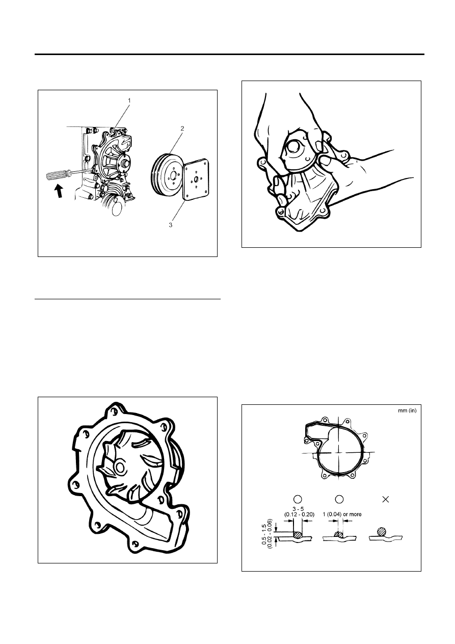
7. Remove the water pump assembly while inserting

and scraping with the driver at the position shown
in the figure.

Legend

1. Water Pump
2. Water Pump Pulley
3. Setting Plate


Inspection

1. External check

• Check for cracks or damage in the pump body.
• Check for cracks and corrosion in the impeller.
• Check for water leakage from the seal unit.
• If you find abnormalities, replace with the water

pump assembly.

2. Bearing nut check

• Rotate the fan center while pushing it along the

radial direction. Confirm that there is no
abnormal noise and no excessive play.

• If you find abnormalities, replace with the water

pump assembly.

Installation

1. Mount the water pump assembly.

• Coat the fluid gasket (ThreeBond 1207C or

equivalent) to a bead diameter 3 to 5 mm (0.12
to 0.20 in) in the groove of the mounting surface
of the water pump.

• Mount the water pump to match with the studs

of the front cover within 7 minutes after coating
the fluid gasket.

• Refer to the figure for the offset in position of

the fluid gasket.

Tighten:

Bolts and nuts to 24 N

⋅m (2.4 kg⋅m/17 lb⋅ft)

N6A6340E

N6A6341E

N6A6342E

N6A6343E

6B-12   Cooling System

2. Temporarily fit the bolts until the water pump pulley

and the setting plate are properly seated in the
water pump assembly.

Legend

1. Fan Pulley
2. Setting Plate


3. Mount the fan belt, tighten the adjusting bolts of

the generator, and adjust the tension.

• Refer to “Drive Belt” in Section 6B.

4. After fan belt adjustments, tighten the generator

using the specified torque.

Tighten:

Nut and bolt to 2 members: 24 N

⋅m (2.4 kg⋅m / 17 lb⋅ft)

Nut and bolt to 3 members: 40 N

⋅m (4.1 kg⋅m / 30 lb⋅ft)

Legend

1. Adjusting Bolt (With A/C)
2. Lock Nut
3. Bolt


5. After the fan belt adjustments, tighten the

temporarily fitted fan pulley and setting plate using
the specified torque.

Tighten:

Bolt to 24 N

⋅m (2.4 kg⋅m / 17 lb⋅ft)

6. Tighten the fan assembly using the specified

torque for mounting.

Tighten:

Nut to 24 N

⋅m (2.4 kg⋅m / 17 lb⋅ft)

Legend

1. Fan Assembly
2. Nut
3. Setting Plate
4. Fan Pulley
5. Bolt


7. Mount the fan guide.
8. Mount the radiator lower hose.
9. Fill the cooling water.

N6A6344E

N6A6339E

N6A6338E

Cooling System   6B-13

Torque Specifications

N6A6345E

6B-14   Cooling System

Thermostat

Components

Legend

1. Radiator Upper Hose
2. Water Outlet Pipe

3. Thermostat
4. Gasket


Removal

1. Drain the cooling water. Prepare the container for

discharging and use it for replenishment when
mounting the thermostat. Set the discharge of
cooling water such that the water does not flow out
of the thermostat housing.

2. Remove the radiator upper hose from the radiator

side.

3. Remove the water outlet pipe.
4. Remove the thermostat.
5. Remove the gasket from the thermostat.

Inspection

• Place the thermostat in water and increase the

temperature while stirring it sufficiently.

• Measure the temperature when the valve is just

opened and when it is fully open.

N6A6346E

N6A6347E


Content   ..  518  519  520  521   ..