Isuzu N-Series. Service manual - part 492


  Index      Isuzu     Isuzu N-Series - service and repair manual


Search            


Content   ..  490  491  492  493   ..


Isuzu N-Series. Service manual - part 492


Engine Mechanical (4HK1-TC)   6A-73
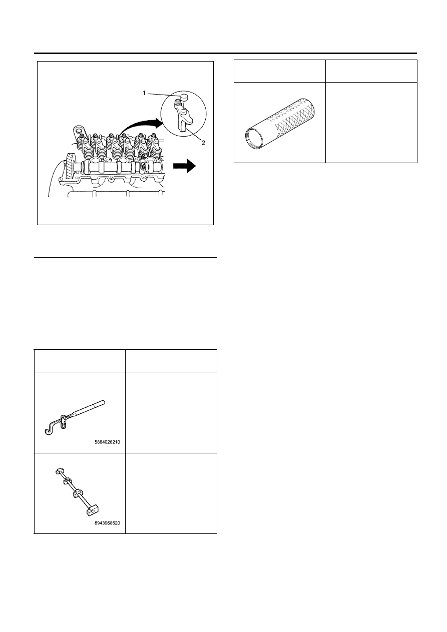
Legend

1. Bridge Cap
2. Bridge


7. Install the camshaft assembly.

Refer to “Camshaft Assembly”.

8. Install the rocker arm shaft assembly.

Refer to “Rocker Arm Shaft Assembly”.

9. Install the cylinder head cover.

Refer to “Cylinder Head Cover”.

Special Tool

Illustration

Tool Number / 

Description / Remarks

5-8840-2621-0 (J-43263)

Valve Spring Replacer

5-8840-2808-0 

(EN-46721)

Pivot Assembly

N6A6093E

5-8840-2833-0 

(EN-47685)

Valve Stem Seal Installer

Illustration

Tool Number / 

Description / Remarks

EN47685

6A-74   Engine Mechanical (4HK1-TC)

Cylinder Head

Component

Legend

1. Bridge Cap
2. Bridge
3. Bridge Guide
4. Split Collar
5. Spring Upper Sheet
6. Valve Spring
7. Valve Stem Oil Seal
8. Valve Guide

9. Idle Gear C Cover

10. Idle Gear C

11. Glow Plug

12. Intake and Exhaust Valves
13. Cylinder Head
14. A/C Compressor Bracket
15. Thermostat
16. Water Outlet Pipe


Caution:
To avoid electric shock; 
Set the switch to the ‘OFF’ position and disconnect
battery negative cable before checking or repairing the
fuel injector, wiring or/and connectors.

Removal

1. Drain the coolant.
2. Remove the engine harness.
3. Remove the front exhaust pipe.
4. Remove the turbocharger.

Refer to “Turbocharger and Exhaust Manifold”.

N6A6120E

Engine Mechanical (4HK1-TC)   6A-75

5. Remove the left-hand EGR adapter and right-hand

EGR pipe.

6. Remove the EGR water feed pipe.
7. Remove the EGR water return pipe.
8. Remove the EGR cooler.
9. Remove the water feed pipe for coolant water for

the EGR cooler and the water return pipe.

Legend

1. EGR Adapter
2. Water Return Pipe
3. EGR Cooler
4. EGR Pipe
5. Water Feed Pipe


10. Remove the fan guide bracket.

11. Remove the left-hand intake pipe between the

inter-cooler and the inlet duct.

12. Remove the A/C compressor drive belt.

• Loosen the tension pulley nut and the adjust

bolt and remove the drive belt.

Legend

1. Tension Pulley Nut
2. Adjust Bolt


13. Remove the A/C compressor.

• Remove the A/C compressor harness

connector, remove the compressor from the
A/C compressor bracket, and fix it with wires
and others.

14. Remove the cylinder head cover.

Refer to “Cylinder Head Cover.”

15. Remove radiator upper hose.
16. Loosen the fuel injector terminal nuts alternately to

the same level, and remove the terminal.

17. Loosen the fuel injector harness bracket bolt,

remove the inside connector, and remove the
harness bracket.

N6A6025E

N6A6121E

N6A6122E

N6A6123E

6A-76   Engine Mechanical (4HK1-TC)

18. Remove the nozzle leak-off pipe (4).

Legend

1. Harness Bracket
2. Harness Connector
3. Fuel Injector Terminal Nut
4. Nozzle Leak-off Pipe


19. Remove the fuel leak-off hose.
20. Remove the fuel leak-off pipe (2).

Legend

1. High Pressure Pipe
2. Leak-off Pipe


21. Remove the water bypass hose from the cylinder

head side.

• Remove the engine coolant temperature sensor

connector.

22. Remove the EGR valve and EGR valve connector.
23. Remove the camshaft position sensor connector.
24. Remove the rocker arm shaft assembly.

Refer to “Rocker Arm Shaft Assembly”.

25. Remove the camshaft assembly.

Refer to “Camshaft Assembly”.

26. Remove the bridge cap carefully so that it does not

fall into inside the engine.

27. Remove the bridge.

Caution:
Store the removed bridge and bridge cap so that they
can be placed in their original locations.

28. Remove the glow plug connector.
29. Remove the glow plug.

N6A6124E

N6A6125E

N6A6126E

N6A6127E


Content   ..  490  491  492  493   ..