Isuzu N-Series. Service manual - part 490


  Index      Isuzu     Isuzu N-Series - service and repair manual


Search            


Content   ..  488  489  490  491   ..


Isuzu N-Series. Service manual - part 490


Engine Mechanical (4HK1-TC)   6A-65

Reassembly

1. Install the knock pin.
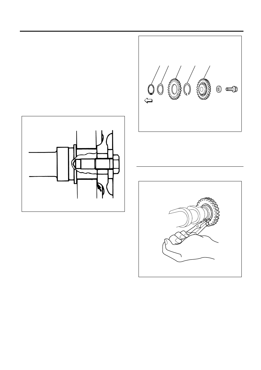
2. Install the camshaft gear.

• With the side of the camshaft gear center boss

part stuck out being on the camshaft side,
install the camshaft gear along with the knock
pin.

Tighten:
Bolt to 142 N

⋅m (14.5 kg⋅m/105 lb⋅ft)

Caution:
Be careful not to damage the cam and journal parts
when tightening up the gear.

3. Install the scissors gear assembly.

• Fix the hexagon portion of the camshaft in a

vise using a mouth ring. Assemble the spring
with its left end contacting the pin of camshaft
main gear to make a gap on the right.

• Assemble the sub gear so that its pin is inserted

into the gap between the right side of pin of the
camshaft main gear and the right end of the
spring.

Legend

1. Snap Ring
2. Dish Washer
3. Sub Gear
4. Spring
5. Camshaft Gear

• Use snap ring pliers to assemble the snap ring

and the dish washer securely.

N6A6102E

1

2

3

4

5

N6A6099E

N6A6098E

6A-66   Engine Mechanical (4HK1-TC)

• Before installing the camshaft to the cylinder

head, rotate the sub gear using the special tool
to prevent the spring force which acts on the
sub gear from affecting. Align the hole of the
sub gear with the camshaft main gear and
install the phase alignment pin from the sub
gear side to match the teeth.
Special tool
Scissors gear spring wrench: 5-8840-2674-0

Installation

1. Turn the crankshaft in the normal direction of

engine rotation until the No. 1 or No. 4 cylinder is
at TDC on the compression stroke.

Notice:
There are 2 timing marks on the crankshaft pulley. 
Mark (1) is near the cylinder block and is used to bring
the 4HK1-TC engine to TDC.
Mark (2) is not applicable to this engine.
Be sure to use mark (1) when bringing the engine to
TDC.

2. Install the camshaft bearing lower.

• Apply engine oil over the camshaft bearing

lower and install it on the cylinder head.

3. Install the camshaft assembly.

• The camshaft assembly ‘B’ mark must be

facing the cylinder head upper face. If not,
serious engine damage will result.

4. Install the baring upper to the bearing cap.
5. Install the bearing cap.

• Apply engine oil on the bearing upper.

N6A6107E

N6A6002E

N6A6003E

N6A6651E

Engine Mechanical (4HK1-TC)   6A-67

• Direct the front mark of the bearing cap toward

the front of the engine and put it together with
the cylinder head in numerical order.

• Apply engine oil to the thread and tighten up the

bearing cap with the prescribed torque.

Tighten:
Nut to 27 N

⋅m (2.8 kg⋅m/20 lb⋅ft)

• Pull out the phase alignment pin of the gear (1)

carefully so that it does not fall into inside the
engine.

Caution:
Be careful not to forget to pull out the phase alignment
pin of the gear.

Legend

1. Phase Alignment Pin

6. Install the rocker arm shaft assembly.

Refer to “Rocker Arm Shaft Assembly”.

7. Install the cylinder head cover.

Refer to “Cylinder Head Cover”.

N6A6109E

N6A6110E

1

N6A6644E

6A-68   Engine Mechanical (4HK1-TC)

Torque Specifications

Special Tool

27 (2.8 / 20)

142 (14.5 / 105)

N  m (kg  m / lb  ft)

N6A6111E

Illustration

Tool Number / 

Description / Remarks

5-8840-2674-0

Scissors Gear Spring 

Wrench

5884026740


Content   ..  488  489  490  491   ..