Isuzu N-Series. Service manual - part 477


  Index      Isuzu     Isuzu N-Series - service and repair manual


Search            


Content   ..  475  476  477  478   ..


Isuzu N-Series. Service manual - part 477


Engine Mechanical (4HK1-TC)   6A-13

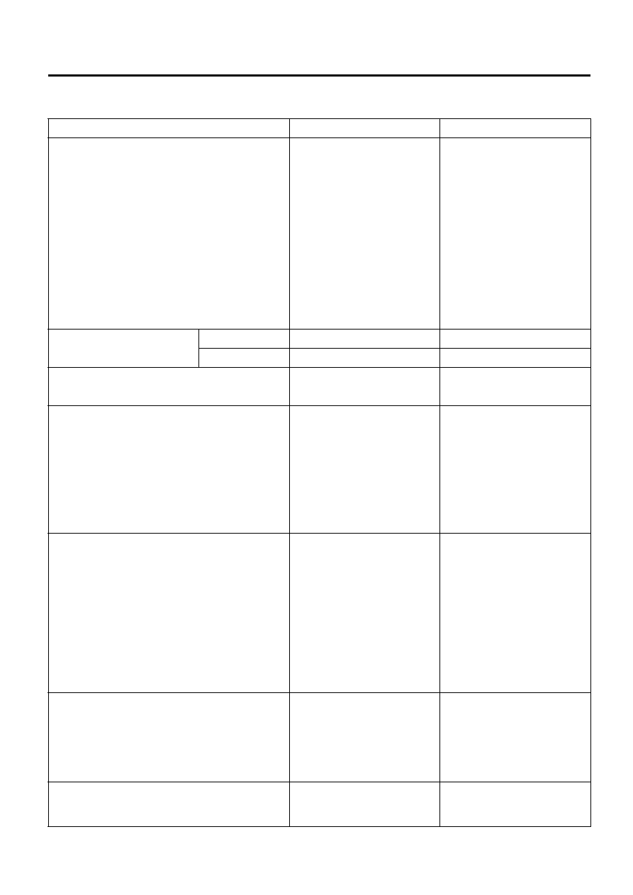
Main Data and Specifications

Item

Engine model 4HK1-TCS

Engine model 4HK1-TCN

Type

Diesel/4-cycle/water cooling 

type in-line OHC

Diesel/4-cycle/water cooling 

type in-line OHC

Combustion chamber type

Direct injection type

Direct injection type

Cylinder liner type

Dry type

Dry type

Number of cylinders -cylinder 
bore 

× strokes

mm (in)

4-115 (4.53) 

× 125 (4.92)

4-115 (4.53) 

× 125 (4.92)

Displacement

cc (cu.in)

5193(317)

5193(317)

Compression ratio

17.5

17.5

Compression pressure

MPa (kg/cm

2

/

psi)/rpm

2.60 – 2.89 (26.5 – 29.5/377 – 

419)/220

2.60 – 2.89 (26.5 – 29.5/377 – 

419)/220

Idling speed

rpm

650 

650 

Valve clearance

Intake

0.4 (0.016) (cold)

0.4 (0.016) (cold)

mm (in) Exhaust

0.4 (0.016) (cold)

0.4 (0.016) (cold)

Ignition type

Compressed ignition

Compressed ignition

Injection order

1 - 3 - 4 - 2

1 - 3 - 4 - 2

Lubricating system

Lubricating type

Pressure type

Pressure type

Oil pump type

Gear type

Gear type

Volume of lubricating oil

Liters (US/Imp

gal.)

13.0 (3.43/2.86)

13.0 (3.43/2.86)

Oil filter type

Full flow filter (cartridge type)

Full flow filter (cartridge type)

Oil cooling type

Built-in-type, water cooling

Built-in-type, water cooling

Cooling system

Cooling type

Water cooling type

Water cooling type

Radiator type

Corrugated fin(pressure type)

Corrugated fin(pressure type)

Water pump type

Centrifugal, belt type

Centrifugal, belt type

Thermostat type

2 wax-type units

2 wax-type units

Thermostat valve-opening 
temperature

°C (°F)

82 (180), 85 (185)

82 (180), 85 (185)

Volume of coolant

Liters (US/Imp

gal.)

17.6 (4.65/3.87) (incl. radiator) 17.6 (4.65/3.87) (incl. radiator)

Fuel system

Injection pump type

Electronic control common rail 

type

Electronic control common rail 

type

Governor type

Electronic type

Electronic type

Timer type

Electronic type

Electronic type

Injection nozzle type

Multi-hole type

7-holes 

φ0.14 mm (0.0055 in) 

inside diameter

Multi-hole type

7-holes 

φ0.14 mm (0.0055 in) 

inside diameter

6A-14   Engine Mechanical (4HK1-TC)

Special Tool

Charging system

Generator type

AC type

AC type

Power output

V-A

24 - 80, 24 - 60, 24 - 50

24 - 80, 24 - 60, 24 - 50

Regulator type

IC

IC

Starting system

Starter type

Reduction type

Reduction type

Power output

V-kw

24 - 4.5

24 - 4.5

Preheat system type

Glow plug

Glow plug

Glow plug standard voltage/
electric current

V

24

24

Item

Engine model 4HK1-TCS

Engine model 4HK1-TCN

Illustration

Tool Number / 

Description / Remarks

5-8840-2008-0

Compression Gauge Set

(J-26999-12 / 

Compression Gauge, 

EN-46722 / 

Gauge Adapter)

5884020080

Engine Mechanical (4HK1-TC)   6A-15

Engine Assembly

Removal

1. Remove a minus (-) terminal of the battery.
2. Drain the coolant.
3. Remove the starter motor.

• Disconnect the front frame harness connector

in the vicinity of the control box of the
transmission and remove each clip that fixes
the harness.

• Remove 2 bolts that fasten the starter and

remove the starter from the clutch housing.

• Fix the starter motor with wire, for instance, in a

place that does not get in the way in removing
the transmission.

4. Remove the transmission assembly.

Refer to “Transmission Assembly”

5. Remove the charge air hose (between

turbocharger and inlet pipe).

Legend

1. Duct
2. Charge Air Hose


6. Remove the inlet hose (between air cleaner and

turbocharger).

7. Remove the charge air hose (between intercooler

and inlet duct).

• Remove the connector of the boost pressure

sensor.

Legend

1. Charge Air Hose
2. Boost Pressure Sensor


8. Remove the upper hose of the radiator.

• Remove the band clip and VSV vacuum hose.

9. Remove a bracket of the fan guide.

10. Remove the fan assembly.

• Remove the nuts and pull them out upward.

11. Remove the heater hoses.

N6A6010E

N6A6011E

N6A6012E

6A-16   Engine Mechanical (4HK1-TC)

• Remove 2 hoses on the engine side.

12. Remove the engine harness.

• Remove the ECM.
• Disconnect the two main harness connectors

from the ECM (For SLD equipped, disconnect
the unsealed connector.)

• Remove the engine ground cable.

13. Remove the A/C compressor.

• Remove the drive belt.
• Remove the connector.
• Remove the A/C compressor and fix it with

wire, for example, to an appropriate place along
with hoses and others.

Legend

1. Fixing Bolt
2. Connector
3. Bracket
4. A/C Compressor


14. Remove the AC generator harness.

• Remove the terminal B cable and harness

connector from the generator.

15. Remove the vacuum hose on the vacuum pump

side.

16. Remove a bracket by the blow-by separator and

remove the harness connector and HBB oil hose
bracket.

17. Remove the blow-by separator hose.
18. To prevent oil from flowing out when the hydraulic

booster brake hose is removed, remove the
fastening bolts for the hydraulic booster brake tank
to lower the tank.

19. Remove one side of the hydraulic booster brake

hose on the high-pressure side.

20. To prevent oil from flowing out when the power

steering oil hose is removed, remove the fastening
bolts for the power steering reserve tank to lower
the tank.

21. Remove the power steering oil hose.
22. Remove the lower hose of the radiator on the

engine side.

23. Hang wire on the engine hanger and hoist to lift up

the engine slightly.

24. Remove the front exhaust pipe.

• Remove the front exhaust pipe from the turbo

and exhaust brake.

25. Remove the fuel hose on the feed and return

sides.

26. Remove the engine mount.

• Remove the fastening bolts for the engine

mount on the chassis frame side.

27. Remove the engine assembly.

• Remove the cab back cover.

Legend

1. Screw
2. Cab Back Cover
3. Nut


N6A6013E

N6A6014E

N6A6015E


Content   ..  475  476  477  478   ..