Isuzu N-Series. Service manual - part 431


  Index      Isuzu     Isuzu N-Series - service and repair manual


Search            


Content   ..  429  430  431  432   ..


Isuzu N-Series. Service manual - part 431


6E-60 EMISSION AND ELECTRICAL DIAGNOSIS

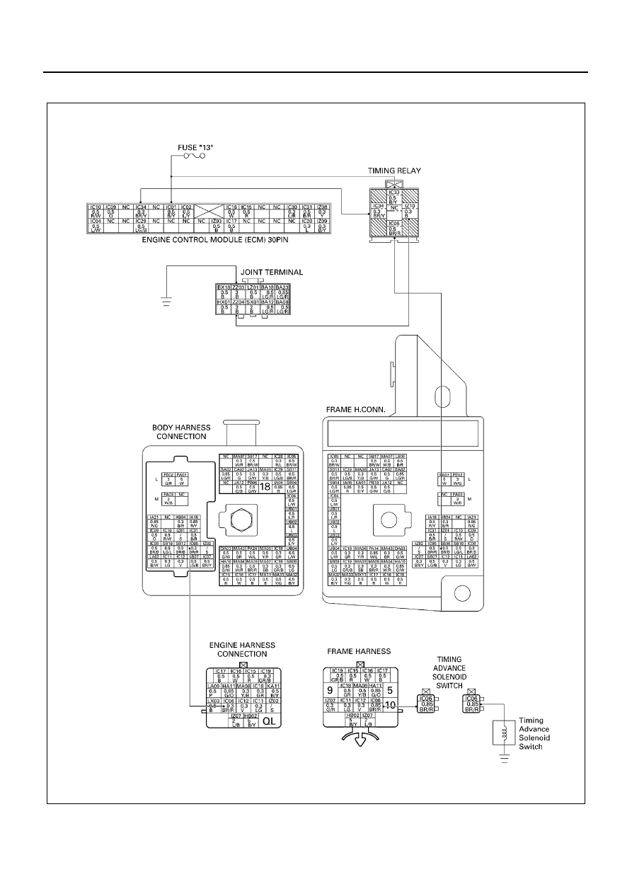
DTC-P23 Solenoid Switch Control Circuit Low Voltage

N6A1173E

EMISSION AND ELECTRICAL DIAGNOSIS 6E-61

Location of Relay

Inspection for Timing Advance Solenoid Switch cut
relay

Legend

1. Relay box (Installed on the instrument panel)

N6A1174E

NO

RELAY NAME

X-5

ABS IND.

X-6

Dimmer

X-7

Power window

X-8

Exh. brake

X-9

Cornering lamp

X-10

Thermo A/C

X-11

Exh. Brake, Charge warning, Key ON

X-12

Heater & A/C

X-13

Buzzer cancel, Heater

X-14

ECU, PTO main, Timing

X-15

Tail, PTO solenoid, M/T

X-16

PTO cut

Legend

A. Timing advance solenoid

N6A1175E

6E-62 EMISSION AND ELECTRICAL DIAGNOSIS

Resistance value

N6A1176E

N6A1177E

Inspection Point

Resistance

Reference

Inspection 
relay unit

←→ 4

240 to 290 (

Ω) (for 12 volt)

256 to 276 (

Ω) (for 24 volt)

←→ 5

Not be supplied electricity

Below 0.5 (

Ω)

Be supplied electricity

←→ 5

Below 0.5 (

Ω)

Be supplied electricity

Not be supplied electricity

Step

Action

Value

YES

NO

1

Was the “on-board diagnostic (OBD) system
check” performed?

Go to Step 2

Go to self diag 

system check

2

1. Ignition “OFF”, Engine “ON”.
2. Jumper the magnetic switch Relay ground

circuit at the Relay connector to chassis
ground.

3. Observe the “Relay; solenoid switch” cir-

cuit open status on the scan tool.

Has DTC23 been corrected?

Go to Step 4

Go to Step 3

3

1. Check for poor connector at the Relay

connector and replace the terminals if
necessary.

Did any terminals require replacement?

Go to Step 11

Go to Step 5

4

1. Check the Relay ground circuit for an

open.

2. If the Relay ground circuit is open, repair

it as necessary.

Was the Relay ground circuit open?

Go to Step 11

Go to Step 2

EMISSION AND ELECTRICAL DIAGNOSIS 6E-63

5

1. Ignition “OFF”, with scan tool disconnect-

ed.

2. Disconnect the Solenoid switch Relay

connector.

3. Apply a circuit tester with voltage range or

a test light to the output line for the Relay.

4. Ignition “ON”, Measure the voltage or

check the test light “ON”. Ignition “OFF”

≥8V or light 

“ON” (for 12 

Volt)

≥16V or light 

“ON” (for 24 

Volt)

Go to Step 8

Go to Step 6

6

1. Ignition “ON”.
2. Disconnect ECM, and check for the Relay

signal circuit terminal connector at the
ECM and clean or replace terminal if nec-
essary.

Did any terminals need to be repaired?

Go to Step 11

Go to Step 7

7

1. Check the Relay signal circuit for an open.
2. If the Relay signal circuit is open, repair it

as necessary.

Was the Relay signal circuit open?

Go to Step 11

Go to Step 8

8

1. Disconnect the Relay.
2. Measure the resistance between the coil

circuit terminals of the Relay.

Is the resistance within specific value?

240 — 290

Ω 

(for 12 Volt)

256 — 276

Ω 

(for 24 Volt)

Go to Step 10

Go to Step 9

9

1. Replace the Relay.

Is the action complete?

Go to Step 11

10

1. Replace the ECM

Is the action complete?

Go to Step 11

11

1. Reconnect all the connectors removed.
2. Ignition “ON”, Engine “OFF”.
3. Ignition “OFF” after 30 seconds.
4. Install Scan tool.

Is DTC 23 all right under Scan Tool Check?

Go to Step 12

Go to Step 2

12

Is any current trouble other than DTC 23 dis-
played by scan tool?

Go to trouble code 

section

Trouble code clear

Step

Action

Value

YES

NO


Content   ..  429  430  431  432   ..