Isuzu N-Series. Service manual - part 393
6C-50 FUEL SYSTEM
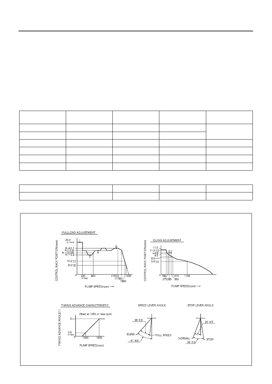
Injection Volume and Governor Performance Diagram
Injection Volume
Timing Advance Specification
Governor Adjustment
Identification Numbers
: 101401-7070/101401-7060
[4HF1 Engine]
Pre-stroke
: No. 1 plunger 4.1
±0.05 mm (0.1614±0.0020 in)
Injection order
: 1 — 3 — 4 — 2 (interval 90
°±30′) Plungers are numbered from the Governor side
Tappet clearance
: Bolt adjustment type
: More than 0.3 mm (0.0118 in) for all cylinders.
: Shim adjustment type
: Manually rotate the camshaft 2 — 3 times and confirm that it
rotates smoothly.
Adjusting point
Pump speed (r.p.m.)
Injection volume (cc/
1000 strokes)
Variance (%)
Remarks
960
61
±1.6
±4
Basic
H
285
16
±1.3
±10.0
A
960
61
±1
—
Basic
B
1,600
(62)
±2
—
C
500
(60.5)
±2
—
I
150
(82)
+16
−0
—
Pump Speed (r.p.m.)
1,050 or less
1,000
1,600 or more
Degree for Angle of Lead (deg.)
Start
0.5 or less
Finish 5
±0.5
N6A0947E