Isuzu N-Series. Service manual - part 391


  Index      Isuzu     Isuzu N-Series - service and repair manual


Search            


Content   ..  389  390  391  392   ..


Isuzu N-Series. Service manual - part 391


6C-42 FUEL SYSTEM

11.  Leak Off Pipe

Tighten:
Leak-off pipe joint bolt to 13 N

⋅m (1.3 kg⋅m / 9.6 lb⋅ft)

12. Nozzle Cover
13. Fuel Feed Hose

14. Fuel Return Hose
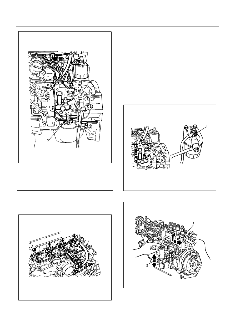
15. Air Bleeding

1) Loosen the priming pump cap (2) at the side of

the injection pump.

2) Loosen the bleeder valve (1) at the top of the

fuel filter.

3) Operate the priming pump to bleed the air from

the injection pump.

4) Retighten the bleeder valve (1).
5) Operate the priming pump.

Check for fuel leakage from around the injec-
tion pump and the fuel filter.

6) Lock the priming pump cap (2) to the injection

pump.

For 4HE1-TC

16. Air Bleeding (4HF1-2 model only)

1) Actuate the priming pump (1) to send the air in

the fuel system to the injection pump.

Legend

1. Fuel pipe joint bolt
2. Fuel pipe joint bolt
3. Clip

N6A0921E

N6A0922E

N6A0923E

N6A0924E

FUEL SYSTEM 6C-43

2) Loosen the sedimenter air bleeding plug (2)

and operate the priming pump until no bubbles
appear.

3) Tighten the air bleeding plug completely.
4) Try to start the engine. If the engine is not start-

ed within 10 seconds, air bleeding should be
conducted once again.

5) Check that there is not fuel leak, and then tight-

en the priming pump completely.

17. Oil Pipe

Tighten:
Oil pipe joint bolt to17 N

⋅m (1.7 kg⋅m / 12 lb⋅ft)

18. Engine Control Lever Assembly

Tighten:
Engine control lever bolt to 24 N

⋅m (2.4 kg⋅m / 17 lb⋅ft)

For 4HE1-TC

19. Engine Control Wire
20. Accelerator Control Cable

1) Check to see if the idling control knob is turned

to the extreme left.

2) Attach the tip end of the cable to the engine

control lever.

3) Pull the outer cable toward the front side of the

vehicle, and provide the engine control wire
and the inner cable with an appropriate play be-
fore fastening the clamp with a nut.

N6A0925E

N6A0926E

N6A0929E

N6A0529E

6C-44 FUEL SYSTEM

4) Check to see if the injection pump control lever

is at the idling position (with the lever in touch
with the stopper bolt).

21. Engine Stop Cable

1) Attach the end tip of the cable to the engine

stop lever.

2) Pull the cable toward the rear side of the vehi-

cle, and fasten the clamp with a nut at the posi-
tion where the lever stops.

22. Oil Level Gauge Guide Tube

1) Install the O-rings to the guide tube lower por-

tion and insert the guide tube completely to the
cylinder body.

2) Tighten the guide tube bolt to the specified

torque.

Tighten:
Guide tube bolt to 13 N

⋅m (1.3 kg⋅m / 9.6 lb⋅ft)

23. Vacuum Hose
24. Intake Air Duct

• Pour coolant into radiator.
• Connect battery ground cable.
• Start engine and check for oil and fuel leakage

carefully.

N6A0929E

N6A0930E

N6A0931E

FUEL SYSTEM 6C-45

INJECTION TIMING ADJUSTMENT

Injection Pump Notched Line Inspection

1. Check the injection pump bracket nuts (1) for

looseness.
Tighten as required.

2. Check that the notched lines (2) on the injection

pump bracket and the timing gear case are
aligned.
If the notched lines are not aligned, the injection
timing must be checked.

3. Same time, check injection timing on the crank

damper pulley. If the injection timing aligned with
incorrect, the injection timing must be readjusted.

Injection Timing Adjustment (Except 4HF1-
2 model)

1. Turn the crankshaft until the timing mark on the

crankshaft damper pulley is aligned with the injec-
tion timing of each engine mode mark in the illus-
tration.

2. Remove the two foam rubbers.
3. Loosen the four injection pump fixing nuts (1).

This will allow the pump to pivot.
Do not bend or scratch the fuel pipe.

4. Align the notched line between the injection pump

bracket and the timing gear case.
Make sure that the timing mark on the crank damp-
er pulley is aligned with correct injection timing.

N6A0932E

N6A0933E

Injection Timing

deg

4HF1

4HE1-TC (4HE1-XS)

BTDC 8

4HG1

BTDC 9

4HG1-T

BTDC 7

BTDC 9 (For Colombia)

4HE1-TC (4HE1-XS)

BTDC 9 (Spec EURO3)

N6A0933E

N6A0935E


Content   ..  389  390  391  392   ..