Isuzu N-Series. Service manual - part 330


  Index      Isuzu     Isuzu N-Series - service and repair manual


Search            


Content   ..  328  329  330  331   ..


Isuzu N-Series. Service manual - part 330


6A-62 ENGINE MECHANICAL

4. Piston Pin

If could not be installed piston pin, it is recommend-
ed to remove it by following procedure.
1) Use a piston heater to heat the piston to 80 —

100

°C (176 — 212°F).

2) Apply a coat of the engine oil to the piston pin.
3) Use your fingers to force the piston pin into the

piston until it makes contact with the snap ring.

4) Check to see if the connecting rod moves

smoothly on the piston pin.
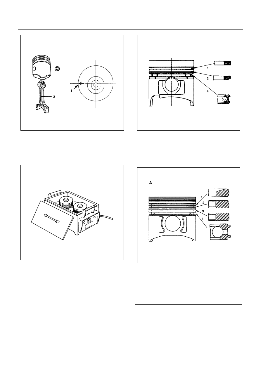
5. Snap Ring
6. Piston Ring

1) Use a piston ring replacer to install the three

piston rings.

Install the piston rings in the order shown in the il-
lustration.

Notice:
Insert the expander coil into the oil ring groove so that
there is no gap on either side of the expander coil before
installing the oil ring.
Install the compression rings with the stamped side fac-
ing up.

2) Apply engine oil to the piston ring surfaces.

N6A0272E

N6A0273E

Legend

1. 1st compression ring
2. 2nd compression ring
4. Oil ring

Legend

A. For 4HE1-TC

1. 1st compression ring
2. 2nd compression ring
3. 3rd compression ring (For 4HE1-TC)
4. Oil ring

N6A0274E

N6A0275E

ENGINE MECHANICAL 6A-63

3) Check to see if the piston rings rotate smoothly

in the piston ring grooves.

7. Connecting Rod Bearing

Carefully wipe any oil or other foreign material from
the connecting rod bearing back face and the con-
necting rod bearing fitting surface.

8. Piston and Connecting Rod Assembly

Notice:
When installing new connecting rod and/or connecting
rod bearings, refer to the selection table. Above works
refer to “CRANKSHAFT” section in this manual.

1) Apply a coat of the engine oil to the circumfer-

ence of each piston ring and piston.

2) Position the piston ring gaps as shown in the il-

lustration.

3) Apply a coat of molybdenum disulfide grease to

the two piston skirts.
This will facilitate smooth break-in when the en-
gine is first started after reassembly.

4) Apply a coat of the engine oil to the upper bear-

ing surfaces.

5) Apply a coat of the engine oil to the cylinder

wall.

6) Position the piston head front mark so that it is

facing the front of the engine.

7) Use the piston ring compressor to compress

the piston rings.
Piston Ring Compressor: 5-8840-9018-0

8) Use a hammer grip to push the piston in until

the connecting rod makes contact with the
crankpin.
At the same time, rotate the crankshaft until the
crankpin is at bottom dead center.

Caution:
Do not bend or damage the oiling jet.

9. Connecting Rod Cap

1) Install the connecting rod bearing caps.
2) Align the bearing cap cylinder number marks

(1) and the connecting rod cylinder number
marks (1).

3) Apply a coat of molybdenum disulfide grease to

the threads and setting faces of each connect-
ing rod cap bolts.

N6A0276E

N6A0277E

Legend

A. Front mark

1. 1st compression ring
2. 2nd compression ring
3. 3rd compression ring (For 4HE1-TC only)
4. Oil ring
5. Coil expander

N6A0278E

6A-64 ENGINE MECHANICAL

4) Tighten the connecting rod caps to the speci-

fied torque.

Tighten:
Connecting rod bearing cap bolt to

• 1st step: 39 N

⋅m (4.0 kg⋅m / 29 lb⋅ft)

• 2nd step: 60

°

• 3rd step: 30

°

Angle gauge: 5-8840-0266-0

10. Oil Pump Strainer
11. Oil Pan
12. Spacer Rubber
13. Cylinder Head Gasket

Above works refer to “CYLINDER BLOCK” section
in this manual.

14. Cylinder Head Assembly

Above works refer to “CYLINDER HEAD” section
in this manual.

Legend

1. Alignment
2. Boss discriminating the front from the rear

N6A0279E

N6A0280E

ENGINE MECHANICAL 6A-65

CYLINDER BLOCK

Component

N6A1624E


Content   ..  328  329  330  331   ..