Isuzu N-Series. Service manual - part 262


  Index      Isuzu     Isuzu N-Series - service and repair manual


Search            


Content   ..  260  261  262  263   ..


Isuzu N-Series. Service manual - part 262


5A4-22 ABS/ASR

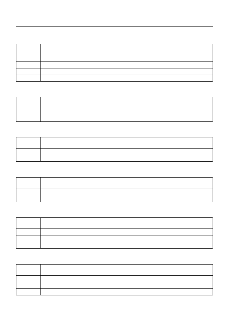
Check List of EHCU Connector Terminal
1. EHCU power supply

2. EHCU ground

3. Brake switch signal circuit

4. ABS warning lamp

5. Front LH speed sensor

6. Front RH speed sensor

Starter
Switch

Tester scale/

range

Connector terminal No. 

to be measured

Standard value

Remarks

OFF

VDC

J-177,3(+)

−J-177,1(−)

0

−0.3V

ON

VDC

J-177,3(+)

−J-177,1(−)

16.5

−34V

OFF

VDC

J-177,2(+)

−J-177,1(−)

16.5

−34V

OFF

VDC

J-177,24(+)

−J-177,1(−)

16.5

−34V

Starter
Switch

Tester scale/

range

Connector terminal No. 

to be measured

Standard value

Remarks

OFF

J-177,1(+)

−GND

0

−1Ω

OFF

J-177,23(+)

−GND

0

−1Ω

Starter
Switch

Tester scale/

range

Connector terminal No. 

to be measured

Standard value

Remarks

OFF

VDC

J-177,16(+)

−J-177,1(−)

0

−0.3V

OFF

VDC

J-177,16(+)

−J-177,1(−)

16.5

−34V

Brake pedal depressed

Starter
Switch

Tester scale/

range

Connector terminal No. 

to be measured

Standard value

Remarks

ON

VDC

J-177,6(+)

−J-177,1(−)

16.5

−34V

OFF

VDC

J-177,6(+)

−J-177,1(−)

0

−0.3V

Starter
Switch

Tester scale/

range

Connector terminal No. 

to be measured

Standard value

Remarks

OFF

k

J-177,32(+)

−J-177,33(−)

1

−2kΩ

OFF

k

J-177,32(+)

−J-177,1(−)

1000k

Ω or more

OFF

VDC

J-177,32(+)

−J-177,33(−)

200mV or more

Tire half-turn/sec

Starter
Switch

Tester scale/

range

Connector terminal No. 

to be measured

Standard value

Remarks

OFF

k

J-177,10(+)

−J-177,11(−)

1

−2kΩ

OFF

k

J-177,10(+)

−J-177,1(−)

1000k

Ω or more

OFF

VDC

J-177,10(+)

−J-177,11(−)

200mV or more

Tire half-turn/sec

ABS/ASR 5A4-23

7. Rear LH speed sensor

8. Rear RH speed sensor

9. ASR cut switch (ASR only)

10. ASR warning lamp (ASR only)

Starter
Switch

Tester scale/

range

Connector terminal No. 

to be measured

Standard value

Remarks

ON

VDC

J-177,22(+)

−J-177,34(−)

0.2

−4.5V

Tire half-turn/sec

Starter
Switch

Tester scale/

range

Connector terminal No. 

to be measured

Standard value

Remarks

ON

VDC

J-177,21(+)

−J-177,12(−)

0.2

−4.5V

Tire half-turn/sec

Starter
Switch

Tester scale/

range

Connector terminal No. 

to be measured

Standard value

Remarks

ON

VDC

J-177,5(+)

−J-177,1(−)

16.5

−34V (switch

pressed)
0

−0.3V (switch

released)

Starter
Switch

Tester scale/

range

Connector terminal No. 

to be measured

Standard value

Remarks

ON

VDC

J-177,30(+)

−J-177,1(−)

16.5

−34V

OFF

VDC

J-177,30(+)

−J-177,1(−)

0

−0.3V

5A4-24 ABS/ASR

Trouble Diagnosis with Scan Tool

Tech 2

Tech 2 is useful to diagnose the electric fault and the
system check of the ABS control system. The Tech 2 is
small and light tester. It can communicate with the ECM
to perform various types of the diagnosis and the test by
connecting the self-diagnosis connector equipped to the
vehicle.

Legend

1. PCMCIA card
2. TECH 2

3. DLC cable
4. SAE16/19 pin adapter

Feature of Tech 2

1. Tech 2 (2) is a 12-V power supply system. Do not

use a 24-V power supply. If the vehicle system is
equipped with a 24-V power supply, use a 12-V
battery with an adapter for power distribution. Pow-
er distribution is not available from the cigar lighter.

2. Set the PCMCIA card (1) to the Tech 2 (2), and at-

tach the VCI (Vehicle Communication Interface)
(3)(4), and connect to the DLC in the vehicle.

3. Turn the power switch off before installing/remov-

ing the PCMCIA card.

4. The capacity of the PCMCIA card for Tech 2 is

10MB. It is ten times as large as Tech1 (1) mass
storage.

5. Tech 2 has a capacity of equivalent to two snap-

shots.

6. The PCNCIA card is sensitive to magnetic and

electrostatic. Please handle it with care.

7. Tech 2 can plot a graph of snapshots.
8. Pressing the EXIT key can bring back to the main

menu anytime.

9. Open the application menu and press the

“F1:Clear DTCInfo” or the DTC clear to erase the
diagnosis trouble codes (DTCs).

How to Connect Tech 2

1. Insert the PCMCIA card for ISUZU system to the

Tech 2 body.

2. Install the SAE 16/19 adapter to the DLC cable.
3. Install the DLC cable to the Tech 2 body.
4. Make sure that the ignition is “OFF”.

N5A2019E

ABS/ASR 5A4-25

5. Connect the SAE-16/19 adapter of the Tech 2 to

the self-diagnosis cord (black) in the body side.

Connect an adapter cable between the Tech 2 and
12-V battery. (When connecting the adapter cable,
start with the negative side.)

Legend

1. 3A-fuse

6. Turn the ignition switch to “ON” and press the

“PWR” key of the Tech 2.

7. Check the display of the Tech 2.

CAUTION:

Make sure that no power is supplied to the Tech 2 when
installing/removing the PCMCIA card.

N5A2014E

N5A2020E

N5A2021E


Content   ..  260  261  262  263   ..