Isuzu N-Series. Service manual - part 260
5A4-14 ABS/ASR
J-9
J-74
J-74
J-75
J-75
J-148
J-148
J-149
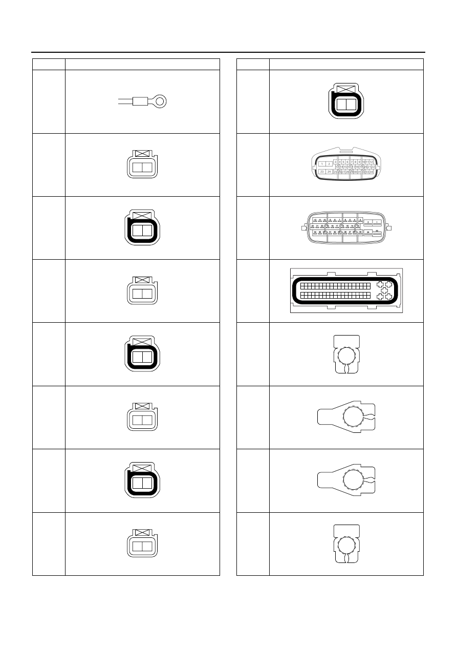
No.
Connector Face
000-001
002-012
1
2
002-011
1
2
002-012
1
2
002-011
1
2
002-012
1
2
002-011
1
2
002-012
1
2
J-149
J-177
J-177
J-191
P-1
P-2
P-3
P-4
No.
Connector Face
002-011
1
2
034-001
034-002
5
6
25
44
63
7
26
45
64
8
27
46
65
9
28
47
66
10
29
48
67
11
30
49
68
12
31
50
69
13
32
51
70
14
33
52
71
15
34
53
72
16
35
54
73
17
36
55
74
18
37
56
75
19
38
57
76
20
39
58
77
21
40
59
78
22
41
60
79
23
42
61
80
24
43
62
81
4
1
3
2
081-001
000-004
000-006
000-006
000-004