Isuzu N-Series. Service manual - part 132


  Index      Isuzu     Isuzu N-Series - service and repair manual


Search            


Content   ..  130  131  132  133   ..


Isuzu N-Series. Service manual - part 132


MANUAL STEERING 3B2-13

3. Gasket
4. Adjuster Screw
5. Adjuster Shim
6. Needle Bearing
7. Sector Shaft

When removing, be careful not to damage the ser-
rations, threads and oil seal.

8. Needle Bearing
9. Oil Seal

10. End Cover
11. Adjuster Shim
12. Ball Nut and Worm Shaft

Always keep ball nut assembly in a horizontal po-
sition and avoid holding it vertically, or ball nut will
slide out.

Inspection and Repair

Make necessary correction or parts replacement if wear,
damage or any other abnormal conditions are found
through inspection.

Visual Checks
Inspect the following parts for wear, damage or other ab-
normal conditions.

• Bearing
• Sector  shaft
• Ball nut and worm shaft
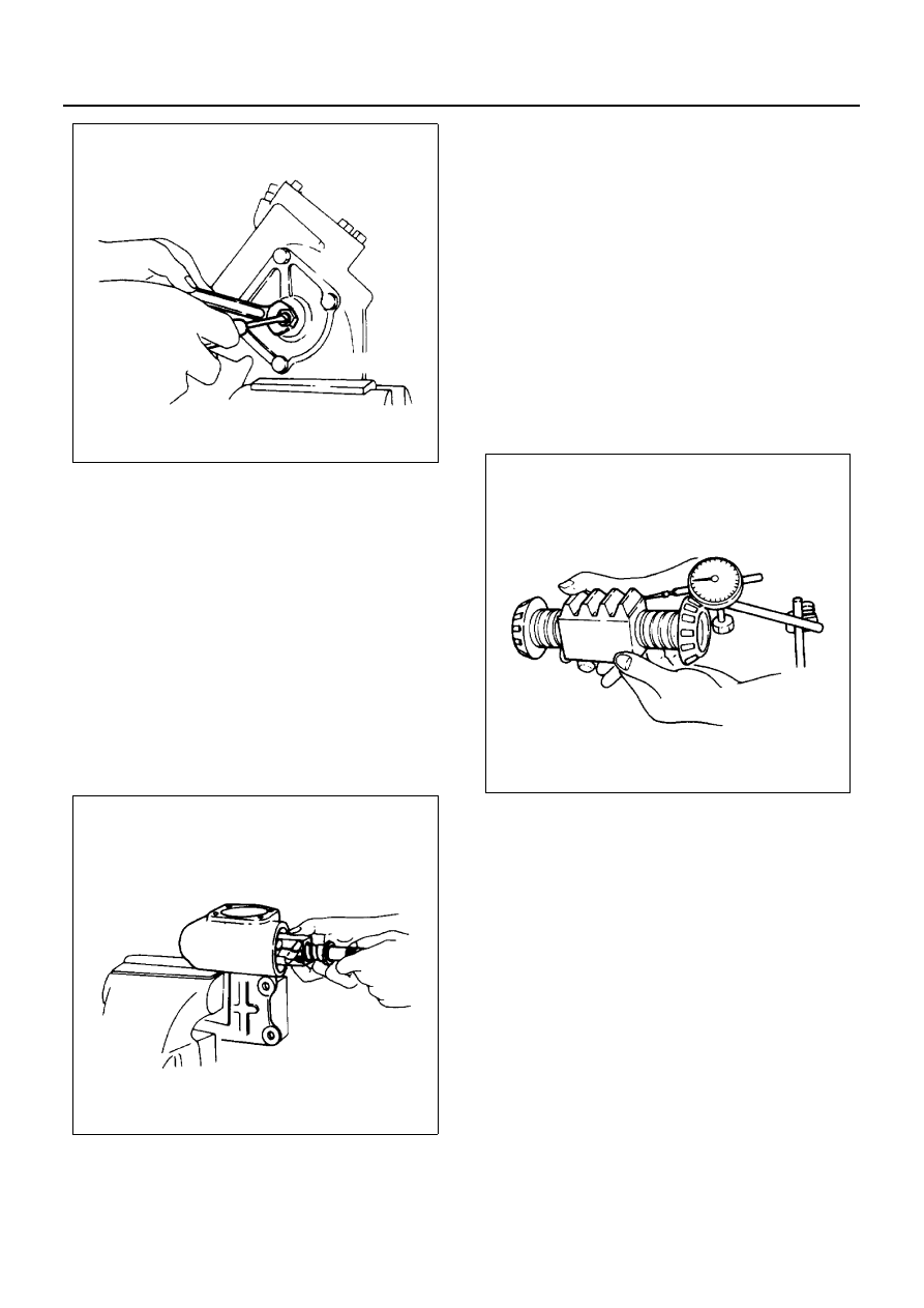
Ball Nut Rotation
Hold the worm shaft vertically and see if the ball nut low-
ers with turning motion smoothly. If lowering of the ball
nut with its own weight is unsmooth, check the worm
shaft for bending and ball-groove for burrs, dents and
presence of foreign matter.

Notice:
When making a test on the ball nut assembly, exercise
care so as not to strike ball nut against end of worm
shaft, or damage to the ball tubes will result.

If any of the parts in the ball nut and worm shaft assem-
bly is found to be defective, the entire parts should be re-
placed using a new worm shaft assembly.
As these parts are of selective combination and are
sealed to prohibit disassembly, the faulty parts should
not be replaced individually.

N3A0285E

N3A0267E

N3A0209E

3B2-14 MANUAL STEERING

Sector Shaft Outside Diameter
Standard : 38.1 mm (1.50 in)
Limit : 38.0 mm (1.496 in)

Sector Shaft and Needle Bearing Play
Limit : 0.2 mm (0.008 in)

Ball Nut Axial Play
Limit : 0.1 mm (0.004 in)

Reassembly

1. Gear box
2. Bearing
3. Bearing
4. Ball Nut and Worm Shaft
5. Adjuster Shim

1) Adjust the starting torque of input shaft by vary-

ing shim thickness.
Steering Shaft Driver : 5-8840-2054-0

Starting Torque
0.29 — 0.69 N

⋅m (0.030 — 0.070 kg⋅m/0.22 — 0.51 lb⋅ft)

Adjust Shims Available
0.01 mm (0.0004 in), 0.02 mm (0.0008 in), 0.05 mm
(0.0020 in), 0.07 mm (0.0028 in), 0.08 mm (0.0031 in)

N3A0289E

N3A0271E

N3A0272E

N3A0209E

MANUAL STEERING 3B2-15

6. End Cover

Tighten:

• Fixing bolt to 44 N

⋅m (4.5 kg⋅m/33 lb⋅ft)

7. Oil Seal
8. Sector Shaft

Align the center tooth (1) of ball nut (2) with that of
the sector shaft (3).

9. Sector Shaft

10. Needle Bearing
11. Adjuster Shim
12. Adjuster Screw

Adjust the clearance and check that the adjuster
screw slides freely.

Clearance
0.1 mm (0.0039 in)
Adjust Shims Available
1.53 mm (0.060 in), 1.56 mm (0.061 in), 1.59 mm (0.063
in), 1.62 mm (0.064 in), 1.65 mm (0.065 in)

13. Gasket
14. Side Cover

Tighten:

• Side cover bolt to 44 N

⋅m (4.5 kg⋅m/33 lb⋅ft)

15. Lock Nut

Adjust the backlash between the sector gear and
ball nut.
1) Install the pitman arm.
2) Set the sector shaft in a straight ahead position.
3) With the adjuster screw, adjust the backlash to

the specification.

Backlash (at End of Pitman Arm)
0.5 mm (0.0197 in) or less

N3A0277E

N3A0192E

Legend

1. Adjuster screw
2. Clearance
3. Shim
4. Sector shaft

N3A0280E

N3A0281E

3B2-16 MANUAL STEERING

4) Lock adjuster screw with lock nut.

Tighten:

• Lock nut to 25 N

⋅m (2.5 kg⋅m/ 1.8 lb⋅ft)

5) Inspect the starting torque of the input shaft.

Starting Torque
0.98 N

⋅m (0.1 kg⋅m/0.72 lb⋅ft) or less

Steering Shaft Driver : 5-8840-2054-0

N3A0298E

N3A0221E


Content   ..  130  131  132  133   ..