Content .. 1306 1307 1308 1309 ..
Isuzu N-Series. Service manual - part 1308
46
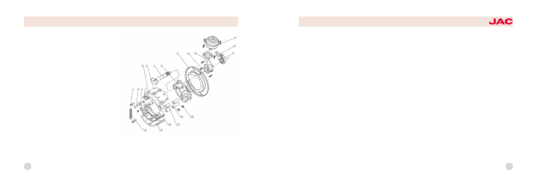
Brake assembly
The function of brake is to utilize
power produced by friction between
brake drum and brake shoe slice to
absorb kinetic energy of vehicle to
decelerate or stop the vehicle. Front
and rear brakes of this brake system
adopt imbalanced structure and are
mainly composed of brake chamber,
brake arm and brake
HFC1048
series trucks
1. return spring locating pin曰 2. roller shaft-brake shoe
3. roller-brake shoe曰 4. gripping ring-brake shoe roller
shaft曰 5/18. front brake shoe with liner assembly曰
6/19. front brake friction plate曰 7. brake cam曰 8. front brake baseboard with liner assembly曰 9. front brake dust cap曰
10. hex bolt曰 11. front brake air chamber support frame with liner assembly曰 12. front left brake air chamber assembly曰
13. hex bolt曰 14. front brake adjusting arm assembly曰 15. shoe shaft fixed bolt曰 16. front brake shoe-shoe shaft曰
17. front and rear brake shoe shaft-liner曰 18. return spring
47
Adjusting arm
1冤Lubrication: mount oil month on
adjusting arm, use lithium base
grease periodically to lubricate ad鄄
justing arm (maximum lubrication in鄄
terval is limited to 10000km), or else,
life of adjusting arm will decrease.
2冤Check adjusting arm's counter鄄
clockwise force moment periodically:
rotate adjusting nut of adjusting arm
counterclockwise when running every
20000km and measure whether the
rotary moment is bigger than 18Nm,
measure for three times repeatedly. If
the moment is smaller than 18Nm, it
indicates adjusting arm has been
damage and needs to be replaced
the adjusting arm assembly.
Brake
Front brake has the same structure
with the rear brake. It is shoe brake
with camshaft with fixed sustainer.
When braking, front and rear shoe
slices of the brake press to the rotat鄄
ing brake drum by the action of the
same push force; so the rear brake
shoe is called power-reducing brake
shoe. All above lead to imbalance of
forces that front and rear brake
shoes press on the brake drum, so
this kind of brake is called simple
imbalanced brake.
Clearance between friction disc of the
brake shoe and the brake drum must
be proper, before adjusting the clear鄄
ance, make the front wheel off ground;
adjusting steps are as follows:
Full adjustment
1. Loosening fixed nut of brake shoe
bearing pin and nut of binding bolt
on cam bracket.
2. Rotate brake shoe bearing pin so
as to make clearance between front
shoe and bearing pin end the same
as that between rear shoe and bear鄄
ing pin.
3. Start braking, make brake shoe
friction disc lean against brake drum
closely and brake camshaft auto鄄
matic positioned and tighten nut of
binding bolt on support frame.
4. Release braking and rotate worm
so as to make brake shoe friction
disc lean against brake drum closely.
Then counter -rotate worm, released
by 3/4r, brake drum should be rotate