Isuzu N-Series. Service manual - part 1306


  Index      Isuzu     Isuzu N-Series - service and repair manual


Search            


Content   ..  1304  1305  1306  1307   ..


Isuzu N-Series. Service manual - part 1306


31

lowed, or else, it can result in the
disability of the pedal尧 deficiency of
the effective travel and incomplete
release of the clutch etc. So the
clutch can not work normally. The
work of air bleeding should be com鄄
pleted by two persons in the best,
one person depress the clutch pedal
in the cab, the other bleed the air in
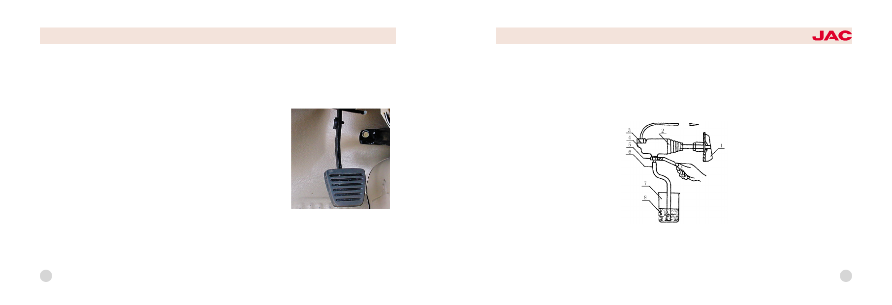
the wheel cylinder. The schematic
diagram of air bleeding for the clutch
wheel cylinder is shown .
Take off the rubber cap of the air
bleed screw on the wheel cylinder,
link a plastic pipe on the air bleed
screw, put the other end of the pipe
into the container filled with brake
fluid, depress the clutch pedal sever鄄
al times, fill the master cylinder and

hydraulic pipeline with brake fluid,
then loosen the air bleed screw, air
bubble can be puffed from the oil
ring if there have air in the pipeline.
Repeat the above-mentioned opera鄄
tion until the air bubble disappear .

Maintenance and adjustment

Long time use or incorrect adjust鄄
ment and incomplete air bleeding of
the clutch can bring the halfway re鄄
lease of the clutch, let the clutch on
the half contact state for long time,
aggravate the wear of the clutch
pressure plate and friction linings.
The decrepitation尧 burnt and exfolia鄄
tion of the friction lining, and the
burnout of the release bearing also
can result in the abnormal operation
of the clutch. When maintenance, all
kinds of clearance of the clutch must
be adjusted. When doing the third
maintenance for the trucks ,you must
clean general/dispant cylinder and
liquid reservoir tank ,then fill grease
to hole of disengaging shaft.

1尧release fork

2尧dust cover

3尧copper washer 4尧wheel cylinder

5尧wrench

6尧soft plastic pipe

7尧container

8尧braking

渊玉冤Clutch

1.Brief description of the struc鄄
ture

The clutch equipped for this series
truck is single -plate dry type di鄄
aphragm spring clutch, outside di鄄
ameter of the driven plate is 椎254.
The hydraulic control unit of the
clutch is composed of the clutch
pedal尧oil storage cup尧 release cylin鄄
der (master cylinder)尧 wheel cylinder
and oil pipe. It is shown in the below
figure.

Adjustment of the clutch operat鄄
ing system

1冤Adjust the limit screw of the clutch
pedal (below figure) to make sure
that the free play of the pedal is 3耀
5mm.

2冤Adjust the mas ter cylinder of the
clutch: loosen the locknut on the
push rod of the master cylinder, ro鄄
tate the end of the push rod to con鄄
tact gently the with piston of the
master cylinder, then rotate the push
rod for 3/4 circle in the contrary di鄄
rection, tighten the locknut of the
push rod, now the clearance be鄄
tween the push rod and the piston is
about 0.5耀1mm.
3冤Adjust wheel cylinder of the clutch
Take off the return spring of the re鄄
lease fork, push the wheel cylinder
piston to the bottom of the cylinder,
loosen the locknut on the push rod,
push the release fork towards the
backside of the engine to the posi鄄
tion where the release bearing and
the release fork contact barely, turn

the spherical nut until it contacts with
the release fork, then turn back the
spherical nut on the push rod for 3
circles, tighten the nut, install the re鄄
turn spring of the release fork.

4冤Bleed air from wheel cylinder of
the clutch
Having air or oil leakage in the hy鄄
draulic pipeline of the clutch is unal鄄

clutch pedal

30

HFC1048

series trucks

渊域冤 Transmission

1.Brief description of the struc鄄
ture

The transmission equipped for the
chassis of this series truck is manual
discontinuously variable transmission
with fixed shaft gear, and it has five
driving gear and one reverse gear.
The synchronizer has been equipped
on the second尧 third尧 fourth and fifth
gear. And the synchronizer is syn鄄
chromesh gear system. The synchro鄄
nizer for the first gear and the reverse
gear is holding mesh gear. Using of
the synchronizer on the transmission
can make the shifting operation con鄄
veniently, decrease the wear and
shock on the gear end, extend the
service life of the gear tooth, shorten

the shifting time, increase the aver鄄
age vehicle speed and reduce the
working intensity of the driver. The
gear shifting operation is accom鄄
plished with the shifting control de鄄
vice of the transmission, which is
shown in the figure on the next page.

2.Shifting control device of the
transmission

The shifting control device of the
transmission is long distance soft ca鄄
ble type with high floor and short lever,
and it take two flexible shaft to imple鄄
ment the gear selecting and shifting
which is shown in the figure on the
next page. It is composed of operat鄄
ing lever seat尧flexible shaft for gear
selecting or shifting and the bracket.
The core shaft of the interior flexible

shaft is steel cable, the operation of
gear selecting or shifting is completed
by the pushing or pulling motion of the
steel cable. The ball on the flexible
shaft and adjusting screw are used for
adjusting the total length of the flexible
shaft to ensure that the gear selecting
or shifting can be to the correct posi鄄
tion. There have symbols of each gear
on the control handle of the transmis鄄
sion, it is shown in the below figure.

32

control handle of transmission

HFC1048

series trucks

33

3.Using and maintenance

1) If found the gear shifting can not
operate or operates difficultly when
the engine is not working, it shows
that the gear shifting lever (or the
flexible shaft) have bad adjustment
or the bolt becomes loose, now you
must adjust the control lever (or the
flexible shaft), check and tighten ev鄄
ery bolt and every nut.
2) If found out-of-gear when running
on the rough road, the control lever
(or the flexible shaft) have bad ad鄄
justment, and it should be adjusted
correctly.
3) If found free play of the control
lever too large, check and tighten
every bolt and every nut.
4) Do not take gear shifting operation

when the engine work at over fast
speed to avoid accelerating the wear
of the synchronizer.
5) When shifting, the force should be
gentle. The hand force must be act鄄
ed on the control lever until the gear
reaches the correct position. Shifting
with flap of one push and one loosen
is inappropriate and the shifting op鄄
eration can not be accomplished
easily in this way.
6) Only after the vehicle stop and
keep steady, the shifting from driving
gear to reverse gear or from reverse
gear to driving gear can be done, or
else, the gear can be damaged.
7) As the fifth gear is over -speed
gear, in order to avoid the damage
of the overspeed gear spoke , its

1尧 gear shift control lever

2尧dust cover 3尧handle

4尧floor of the cab

5尧flexible shaft for gear selecting

6尧transmission rocker arm for gear

selecting

7尧side bracket for gear selecting

8尧flexible shaft for gear shifting

9尧fixed bracket of the gear shifting

flexible shaft

10尧rear cover of the clutch

11尧transmission rocker arm for gear

shifting

schematic diagram of the transmission

gear shift control device

34

running speed is under 50 km/h, the
fifth gear can be used .
8) When running, if find there is ab鄄
normal noise in the transmission,
stop the vehicle and check it, elimi鄄
nate the malfunction.
9) When sliding on the downgrade,
stalling of the engine is unallowed,
starting the engine with the inertia of
sliding on the downgrade is forbid鄄
den to avoid the damage of the gear
and the synchronizer.
10) In the running -in period of the
new vehicle, because the metal
chipping which was produced by the
frictional function between new parts
is bad to components in the trans鄄
mission, especially to the life of the
conical ring on the synchronizer, so

the lubricating oil should be replaced
after the running -in period of the
new vehicle expires. Under general
condition, for every 6000 km running,
replace the lubricating oil once.
When replacing the lubricating oil,
first drain the oil in the transmission,
prop up the rear axle, shift the trans鄄
mission into the reverse gear, add
the kerosene, rotate the transmission
for 2耀3 minutes, then drain the kero-
sene, add the pure gear oil.
11冤 Check the oil level in the trans鄄
mission frequently, if found the level
is under the lower edge surface of
the oil filler bolt hole, sufficient oil
should be added.
12冤 Check the outside bolt of the
transmission and the flange of the

second shaft for tightness and the
operating state of the component in
the transmission frequently, because
the vent plug is blocked by dust and
pressure in the transmission increas鄄
es, the oil seepage or leakage may
be found, so the vent plug should be
cleaned periodically.
13冤 The movement parts of shifting
operation should be kept good lubri鄄
cating, or else, the shifting operation
may become difficult because of the
wear of the movement parts. If found
the position of gear selecting is in鄄
correct, or gear shifting become dif鄄
ficult or the transmission is out of
gear automatically in using, firstly
you should readjust the gear select鄄
ing and gear shifting mechanism.

HFC1048

series trucks

35

(芋) Drive shaft

1.General structure

The two-piece driveshaft, connected
with transmission on the front end
and with rear axle on the back end.

2.Use & Inspection

1冤Driveshaft has been counterpoised
in factory, it should be ensured not to
be impacted in use and not to be
knocked and stacked in disassemble
and carry. Replace if the shaft is dis鄄
torted or the balancer is desquamat鄄
ed, otherwise there will be vibration,
noise, and extra impact in travel, it
can damage power train and endan鄄
ger driver.
2冤Regularly check the cross shaft
needle bearing, check the sealing of

the slide spline and replace the oil
seal when necessary
3冤The first maintenance ,to fill grease
to universal joint ,slide spline ,oil pis鄄
tol ,driving spindle and quickly tight
the blot in order to sliding the univer鄄
sal joint .According to moment ratio
to checking and tighten driving spin鄄
dle and the middle parts of bearing
blots.
The second maintenance ,to check鄄
ing is there anything fall down about
the dirt proof boot ; is there any
problems about move the universal
joint .when cross shaft in the middle
of the needle bearing .The distance
would not be very large .If it is too
large ,you would be disassemble the
universal joint and you can depend

on what you need to changing nee鄄
dle bearing universal joint.
When you do the third maintenance ,
should be disassemble the driving
spindle .Pay attention to sign on
flange ,cross shaft ,link fork, slide
spline in order to mounting .When
you finished all the maintenances ,
please do the blance check , the
standard of dyramic blance is 2750
r/min.The amount of unbalance is
more than 144g.cm遥

渊IV冤 Rear axle

The brief of structure 院Single reduc鄄
tion rear axle ,as the final part of
power train of truck ,is the driving
axle ,and it is composed of final
drive and differential and axle hous鄄
ing .Final drive can not only change

36

the direction of driving force ,but also
reduce the rotate speed .It is com鄄
posed of drive pinion and driven
gear and final drive .The drive pinion
is composed with drive shaft ,whose
end with spline is connected with uni鄄
versal joint assembly by coupling
flange .Center support is mounted in
two opposite conical bearing ,so that
it can suffer not only radical bearing ,
but also axial force. Drive pinion,
whose small-end journal mounted in
direct tapered roller bearing, can on鄄
ly support radial force. It is fixed on
the flange which located on top left
of differential case by several bolts.
A differential, composed of differen鄄
tial case and cross and four side pin鄄
ions, let the left wheel rotate at a dif鄄

ferent speed from the right wheel.
Rear one -piece banjo style axle
housing is made by means of weld鄄
ing punched armor plate.
Meshing of tooth face and clearance
adjustment of final drive
(1) Check drive pinion bearing for
pretension .The pretightening force of
drive pinion bearing should be ad鄄
justed. Measuring in the bolt hole of
drive pinion bearing case, the tan鄄
gential pull should be 15~30N.
(2)The pretightening force of drive
pinion bearing can be adjusted by
means of adding and reducing ad鄄
justing shim. Add shim can decrease
friction torque, while reducing shim
can increase it. There are three kind
of shim according to thickness

(0.40mm, 0.45mm, 0.5mm).
(3) Check final drive for meshing be鄄
tween drive pinion and driven gear.
The contact area and side play be鄄
tween drive pinion and driven gear
can be adjusted by means of adjust鄄
ing shim and adjusting collar of dif鄄
ferential bearing. There are three
kind of shim is 0.30mm and 0.4mm
0.45mm, and the 0.5mm Normally,
the clearance between these two
gears is 0.15~0.25mm, while the side
play ranges under 0.07mm. To adjust
side play, measure four points with
equal angle around the driven gear,
and the gauge outfit of micrometer
should be in a vertical position. To
adjust tooth contact area, driven gear
should be coated with red lead at

HFC1048

series trucks

37

three points, and 2 ~3 teeth should
coated at every point. Then rotate
gears clockwise and anti -clockwise
to get the trace of contact area (see
the right figure).
The teeth area is not suit the figure
(a)which should be adjust it .If the
trace is slanting to the convex or
concave then adding the shims ;if
the trace is slanting to the convex or
concave ,then reducing the shims.
Normal trace should be near the
small end ,as figure (a):Add shim if
trace near the convex or concave
tooth root ,as figure (b)曰Reduce shim
if trace near convex or concave tooth
top , as figure (c).
Adjust the wheel hub bearing of rear
axle: to locking bearing and nut ,then

release1 辕 3要1 辕 4circle遥 Tighten the
force moment to 490要588N.m

Use & maintenance

1冤Lubricate for hyperbola bevel gear
is very strict, can be only specified
gear oil. Don't use or mix with other
gear oil, or will result in quickened
scratch and wear.
2冤Don't remove or adjust the gears

and bearings of final drive, for they
have been matched and adjusted in
factory. Do these only when gear
worn and free play is beyond the
limit value, or when bearing axial
clearance is beyond the limit, or
when some of parts damaged.
3冤Clean the vent plug regularly,
make sure that ventilation is expe鄄
dite. A jammed air drain can bring
higher air pressure in rear axle, and
it will result in lubricant leak from the
drive pinion seal and other welding
line.
4冤Check the lubricant level in axle
housing regularly. Check the lubri鄄
cant for quality regularly, and replace
if the chroma and viscosity is abnor鄄
mal.


Content   ..  1304  1305  1306  1307   ..