Isuzu N-Series. Service manual - part 1305


  Index      Isuzu     Isuzu N-Series - service and repair manual


Search            


Content   ..  1303  1304  1305  1306   ..


Isuzu N-Series. Service manual - part 1305


22

Notice院

The details of the engine structure尧 assembling尧 adjustment尧 using and maintenance can be consulted in the oper鄄

ating specification of relevant engines.
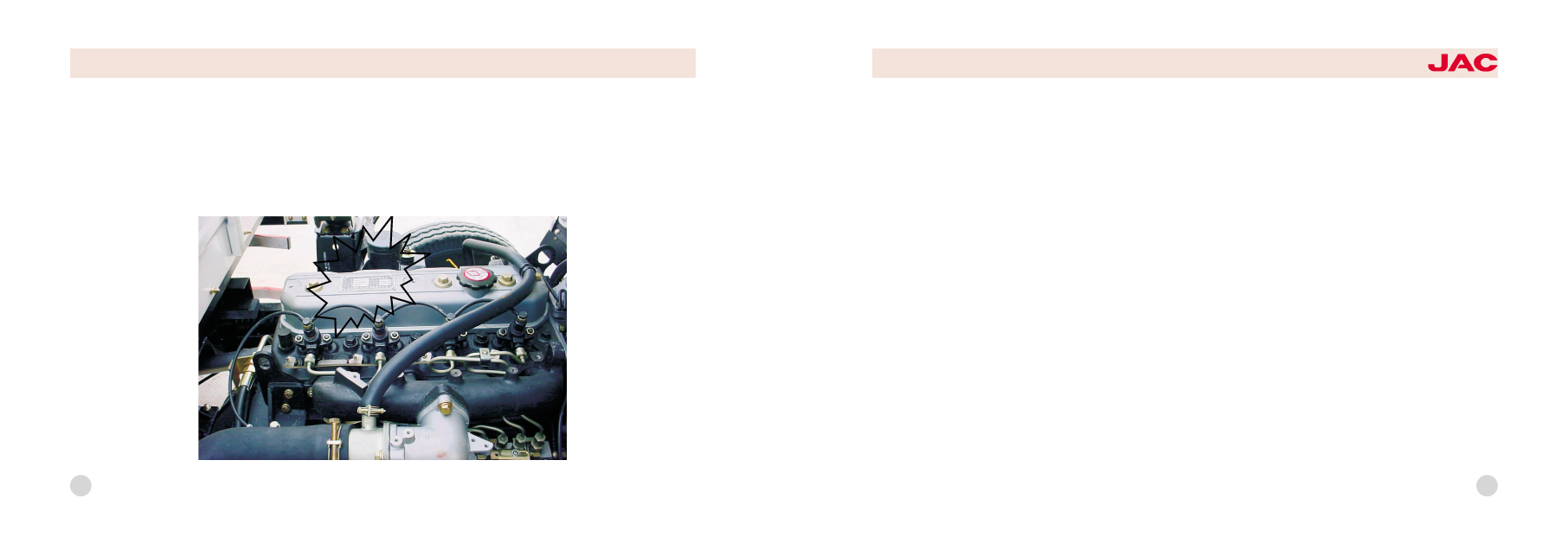
The position of the engine card
Cause院The card of engine is on the top cylinder head or on the side of engine .It writes the model number of engine ,
sequence number ,declared power ,declared speed and the factory date .Pay attention to find it in order to using it
clearly and convenience.(as picture)

HFC1048

series trucks

23

(玉). Inlet air尧 exhaust sys鄄
tems

1. Brief description of the struc鄄
ture

Inlet system includes air inlet pipe
assembly尧 air filter assembly尧 intake
manifold. Exhaust system includes
exhaust pipe尧 muffler and exhaust
tailpipe
Use and maintance院
1) The service life of the engine has
great relationship to the workmanship
of the air filter. Absolutely forbid that
the engine works without air filter or
on the condition that the air filter is
disabled. Taking the intake opening
of air filter as the original intake open鄄
ing is forbidden.

2) For every 1000km running, check
the inlet and exhaust manifold for the
following:
a. Check nuts for looseness, when
tightening the nut on the inlet and
exhaust manifold, the torsion force
should be equable, or else the air
leakage can occur.
b. Check the inlet and exhaust mani鄄
fold for crack and hole, check the
gasket for damage and erosion, if
found, replace it with a new one.

Air filter

The function of air filter is to filter out
the dust and the sand in the air en鄄
tered into the engine.
Air filter is cyclone dust gathering air
cleaner with paper filter element. Af鄄
ter external air enters into the air filter

through the air inlet pipe, larger dust
particle can be separated from the
air by the function of cyclone vane,
then can be thrown into the dust
gathering plate, the separated air
keep on moving and enter into the
cylinder by the filtering function of
the paper element.
For every 1000km running, check
and maintain the air filter. When run鄄
ning in the condition of excessive
dust, the running mileage interval for
inspection and maintenance should
be shortened suitably.
Cleaning of the air filter:
1) Remove the dish-shaped nut from
the end cover. Take away the end
cover, remove the inner nut and take
off the filter element assembly.

24

2) Clean the cover cap and the inner
part of the housing with dry and
clean cloth.When cleaning, do not let
the moisture enter into the air filter.

3) To cleaning dust unloading valve
in order to usage well .
4) Tight and close the rubber of
connected brake .
5) Clean the air filter element: clear
away the dry dirt or dust with com鄄
pressed air gun (air pressure should
be less than 690kpa),blow from the
inner side of filter element towards
outside. Do not clear away the dirt or
the dust with beating or knocking.

(域). Cooling system

1.Brief description of the struc鄄
ture

Cooling system is closed water cool鄄
ing pressure cycle type. It is com鄄
posed of radiator尧coolingfiuid尧ther鄄
mostat尧 fan 尧bulge radiator and wa鄄
ter inlet and outlet pipes of radiator.

The concrete structure and type of
the cooling system components can
be consulted in detail in the operat鄄
ing specification of relevant engines.

2.Using and maintenance of co-
oling system

1) Recommend using long effective
antifreeze preservative liquid for cool鄄
ing fluid. In the north, it can avoid the
damage of engine because of the
freezing of cooling fluid in winter; in
the south, it can increase the boiling
point of cooling fluid in summer to
avoid the damage of engine over鄄
heating because of air resistance in
high temperature.
2) Before dispatch the vehicle every
time, check the liquid level in the ra鄄
diator and in the bulge radiator, if

1尧cab 2尧vent hose (1) of the air filter

3尧intermediate connecting pipe

4尧connection board

5尧vent hose of the air filter

6尧right longitudinal member of the frame

7尧air filter bracket

8尧intake pipeline of the air filter

9尧connecting hose 10尧air filter

schematic diagram of air filter

HFC1048

series trucks

25

found it is not enough, add liquid to
the specified height.
3) Drainage of cooling system. In
cold region and in winter, without us鄄
ing antifreeze preservative liquid, if
long time parking or receiving the
vehicle everyday, the cooling system
must be drained. And you should
open the water filler cap of the radia鄄
tor to avoid the incomplete drainage
of cooling water.
4) After engine operating for long
time, furring can produce in the
cooling water and it should be
cleaned in time. Clean it with follow鄄
ing method: mix 700 耀800 gram
caustic

soda

and

150

gram

kerosene, add the mixture liquid into
the cooling water, run in medium

speed for 5 耀10 minutes, then after
stopping for 10耀12 hours, restart the
engine and run for 10 耀15 minutes.
Then drain the aqueous solution and
clean the cooling system with
cleaned water.

3.Advertent proceedings in using
long effective antifreeze preser鄄
vative liquid

1) Choose suitable antifreeze liquid
according to the minimum tempera鄄
ture of the region, if the minimum
temperature of the region is -25益 ,
antifreeze liquid whose solidifying
point is -30益 should be chosen.
2) When compensating antifreeze
preservative liquid, choose the same
model to avoid deposition.
3) If find deterioration of antifreeze

preservative liquid, replace it entirely
at once. The color of antifreeze liquid
is green or blue, if having deteriorat鄄
ed, the color should be dull red be鄄
cause of impurity infiltration.

To adjusting the degree of ten鄄
sion of the fan belt

1.The disadvantage of engine is
tighten or lax the fan belt .Before use
it please read the operating specifi鄄
cation .
2.The way of adjustment :firstly to
adjusting blots ,secondly to adjusting
,third to adjusting the tight of
wedge -shaped belt .Using finger
press way ,to pressing for 98/N .The
standard of crankshaft pulley is 25要
31mm .The standard of fan belt is
7要8mm.

26

(芋) Accelerating transmis鄄
sion system

1.Brief description of the struc鄄
ture

Accelerating transmission equipment
is composed of accelerator pedal
mechanism尧 accelerator wire draw鄄
ing and acceleration governor arm of
the engine. It is shown in the figure in
the above page.
When depress the pedal, driving
medium of the mechanism pull the
wire drawing, control the opening
extent of the accelerator to increase
or decrease the speed
1冤 Accelerator pedal mechanism:
Accelerator mechanism take the
newest structure of ISUZU truck. It
operates simply and reliably and has
accelerating wire drawing and hand
throttle wire drawing; the pedal is the
structure with injected molding and it
has the trait of convenient assem鄄

bling and little operating noise.
2冤Accelerating wire drawing:
It operates by the soft wire drawing.
And it has traits of reliable structure尧
convenient layout尧 little frictional re鄄
sistance and stable transmission.
3冤Hand throttle wire drawing:
Using with the foot throttle can quick鄄
en the preheating of the engine or in鄄
crease the idling speed.

2.Using and adjustment

1) Check the chucking position of the
linkage rod and the accelerator
mechanism for rightness and reliabil鄄
ity, check the direction of the wire
drawing for straight and check on
the cornering for smooth transition.
2) The pedal should be depressed
easily and to the extreme position

1尧stalling wire drawing 2尧assembly

of accelerator mechanism and pedal

3尧front floor of the cab

4尧acceleration wire drawing

5尧stalling oscillating arm of the engine

6尧acceleration oscillating arm of the

engine 7尧frame

schematic diagram of accelerating

transmission equipment

HFC1048

series trucks

27

without jamming. When releasing the
pedal, it should be returned freely.
3) When depressing the pedal, if the
free play is too big or the opening
extent of the accelerator is not e鄄
nough, adjust the position of bolts.

渊郁冤 Fuel supply system

1.Brief description of the struc鄄
ture

Fuel supply system is composed of
fuel tank尧 fuel filter尧 fuel pump尧fuel
inlet line and fuel return line.
The function of the fuel supply sys鄄
tem is to inject the specified quantity
diesel fuel of specified pressure and
good atomization into the cylinder at
the correct time with definite interval
of injection according to the operat鄄
ing requirement, and take good com鄄

pression ignition with the air rapidly.
Its operating state has important in鄄
fluence to the power and economy
performance of the engine.
1) Coarse cleaner院the car's fuel pip鄄
ing have a DX150T spin-on oil filter袁
flow volume is 1.5L/min. It can transi鄄
tion impurity and can separate water
and oil

2) Fuel tank:. The tank install the filter
gauze inside the fuel filler port to pre鄄
vent impurity of large particle enter鄄
ing into the fuel tank, set oil drain
plug on the bottommost position of
the fuel tank to drain the deposit and
water on the bottom of tank when
cleaning the fuel tank.

Using and maintenance of coar-
se cleaner

1冤To tight all the pipe line .
2冤When the DX150Tprecipitator wor-
ks for 1000/km and 200hours, to wa鄄
terproofing.

diesel precipitator

29

芋尧Chassis

渊玉冤Clutch

渊域冤Transmission

渊芋冤Drive shaft

渊郁冤Rear axle

渊吁冤Frame

渊遇冤Suspension set

渊喻冤Front axle

渊峪冤Steering system

渊御冤Brake system

渊愈冤Wheel & Spare wheel riser


Content   ..  1303  1304  1305  1306   ..